


I just purchased a 4th axis from Novakon for my NM200. Can anyone with a 4th axis provide me with a mach3 profile so that I can understand how to configure it?
Thread: 4th axis
Results 1 to 20 of 75
-
05-01-2015, 01:07 PM #1
 Registered
- Join Date
- Dec 2009
- Posts
- 594
 4th axis
-
05-07-2015, 01:09 AM #2
Registered
- Join Date
- Mar 2011
- Posts
- 805
Re: 4th axis
i am about to install 4th axis sitting in the box for two years .... if you get it working please share the profile .... hate to reinvent the wheels. thx
-
05-07-2015, 02:55 AM #3
Registered
- Join Date
- Mar 2011
- Posts
- 480
Re: 4th axis
Cool! keep us updated. I would love to make a fourth axis horizontal tombstone if my production numbers could justify the cost. Originally Posted by kvom

-
05-07-2015, 12:16 PM #4
Registered
- Join Date
- Dec 2009
- Posts
- 594
Re: 4th axis
John said he would send me a modified copy of my profile. Haven't received it as yet.
-
05-08-2015, 09:30 PM #5
Registered
- Join Date
- Dec 2009
- Posts
- 594
Re: 4th axis
I received the XML file from John and will try the 4th axis this weekend.
-
05-09-2015, 05:20 AM #6
Registered
- Join Date
- Mar 2011
- Posts
- 805
Re: 4th axis
did you already installed the hw? if yes, can you post a picture? i am debating on motor positioning ... left or right. did you face any issue with hw installation? Originally Posted by kvom
i also talked to john and i think i have functional profile.
all,
do autocad inventor hsm 2016 support fourth axis toolpath? if yes, which post processor should i use for mach3? please point me to right direction.
thx
-
05-09-2015, 12:43 PM #7
Registered
- Join Date
- Dec 2009
- Posts
- 594
Re: 4th axis
Haven't installed hw yet, probably Sunday.
Most work I intend will just have manual g-code as the moves are simple (e.g., gear cutting). For cylindrical engraving or milling I'd generate g-code as for a flat piece, and then use a wrapper program to convert Y moves to A moves. For this to work, the g-code needs to have no G2 or G3 moves, so CAM needs to do arcs as short G1 segments.
-
05-10-2015, 12:25 AM #8
Registered
- Join Date
- Dec 2009
- Posts
- 594
Re: 4th axis
Unboxed the rotab today and found that the end of the cable from Novakon had the wrong pin config. Hopefully I can get a new cable soon.
-
05-10-2015, 12:08 PM #9
Registered
- Join Date
- Dec 2009
- Posts
- 594
Re: 4th axis
It turns out that the cable I have is correct. There are two plugs on the motor, just needed to find the right one. Just did very quick test last night to verify that the table moves on command.
To jog, the F and R keys move forward and back, with the jog increment specified in degrees. It's quite slow: 1 degree jog is 10 seconds. G0 A10 takes 12 seconds, so much faster. My machine's rapids are only 75 ipm, so that may have some bearing.
-
05-10-2015, 11:57 PM #10
Gold Member
- Join Date
- Sep 2009
- Posts
- 1856
Re: 4th axis
on my 4th I have it set to 4000 mm/min what makes it the same as the other axis in the speed that they move the other are 1250 mm/min, 157 ipm, 49ipm
http://danielscnc.webs.com/
being disabled is not a hindrance it gives you attitude
[SIGPIC][/SIGPIC]
-
05-11-2015, 11:21 PM #11
Registered
- Join Date
- Dec 2009
- Posts
- 594
Re: 4th axis
Unit is basically your Chinese 8" rotary table with the manual handle replaced by a stepper motor. Mill's controller already had the electronics to drive it, so it was pretty much plug and play. John provided me with a Mach3 profile that had the basics for controlling it, and I just needed a few configuration mods to get it moving.
First job is to mount a chuck to the table. With the table mounted horizontally I centered it under the spindle.
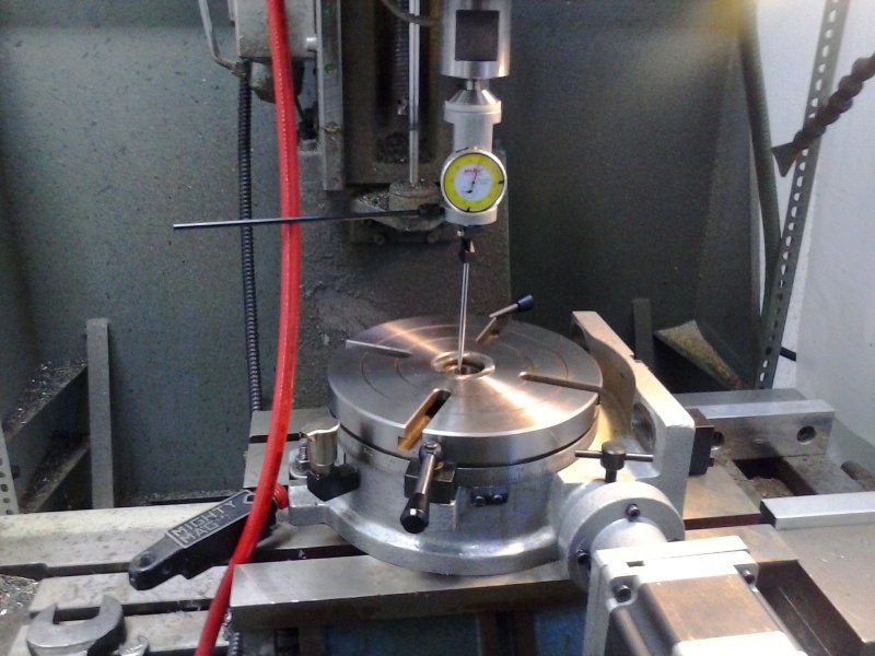
That turned out to be a waste of time since I found that I didn't have enough Z space to use the same center finder with a rod held in the chuck. So went to plan B using a DI to center the chuck, which I just moved from my old manual rotab.
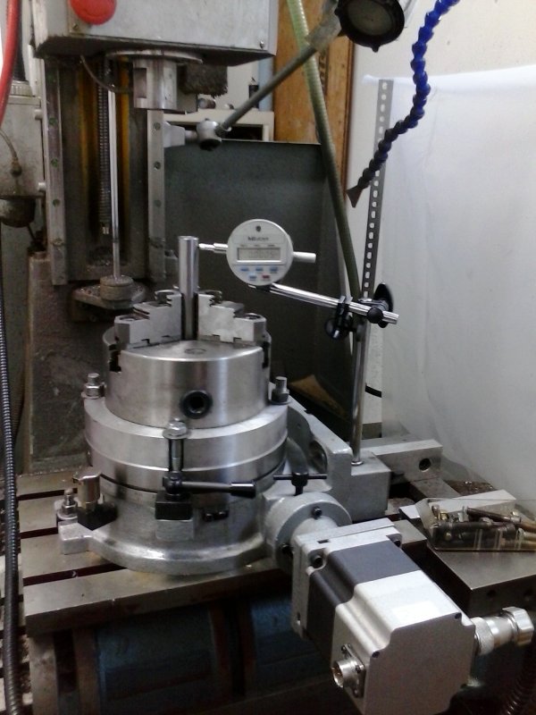
Managed to get it aligned to less than .001" all around, so quite happy with that. Then set it vertical.
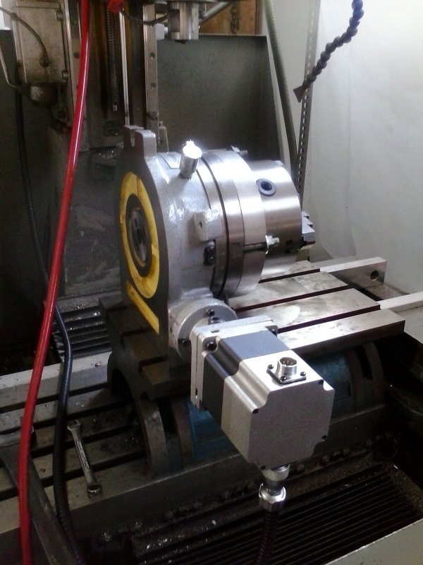
As can be seen, the motor extends out a long ways. I might need to turn it the other direction because the tailstock wants to point from the left:
I suspect that once the aligned the tailstock can be operated OK with its back to me.
-
05-12-2015, 12:38 PM #12
Registered
- Join Date
- Mar 2011
- Posts
- 805
Re: 4th axis
Thanks for posting the pictures. As I suspected, motor projection is forcing you to put the table on the right side. I did not understand your comment about tailstock. When I put it on the left side, lever is on the back ....
Why you have to find the center? I thought only calibration would be to make sure that table is horizontal and vertical compared to spindle.once installed on the side. Am I missing something?
I know there is a place to put in the oil but I saw in Tormach video that person has to oil from two small openings as well. Did you have to do anything to adjust backlash?
In my case, moving the lift table from basement to garage took the toll and guess I will have to wait at least till next weekend to attempt to install the fourth axis.
thanks again
-
05-12-2015, 01:18 PM #13
Registered
- Join Date
- Dec 2009
- Posts
- 594
Re: 4th axis
My case is a bit different since I have to use the riser table to get it high enough for the spindle to reach (NM200 with tall column). So I don't have an easy way to mount the tailstock. For cutting gears you don't need the tailstock anyway. On a more standard mill I'd mount the axis on the right side with the motor facing to the rear. I believe it won't hit the column unless you're using very large stock. The motor to the front would likely hit most enclosures.
Once the tailstock height is set, it probably would not need to be adjusted for normal use.
The reason I did the center finding at first was to be able to use the coax center finder in centering the chuck. But since I couldn't get the spindle high enough for that I went to the DI method.
You'll notice an oil cup in the 1st and 3rd photos. I put in some spindle oil when it was horizontal, but when vertical I removed the elbow and screwed in the cup directly. There is a ball oiler on the side of the table, and I got a bit of oil in there too. A disadvantage of having the motor at the front is that the oil sight glass is on the back.
The backlash is adjusted by turning the motor mount. This was a very finicky process. Turn too little or too far and you get no motion or jerky motion. I issued a G0 A360 command in Mach and then jiggled the motor until I found a smooth spot, then tightened the lock screw. Took several tries.
I removed the two table lock assemblies as they serve no real purpose for this application.
-
05-12-2015, 01:39 PM #14
Registered
- Join Date
- Mar 2011
- Posts
- 805
Re: 4th axis
Thanks. I sure will be looking at the pictures again very soon.
It is been long since I played with Mach3 settings but if my memory is any good we do need to change Mach3 setting if table is mounted on the right side instead of left. right?
thanks for all the help.
Regards,
-
05-12-2015, 01:45 PM #15
Registered
- Join Date
- Apr 2005
- Posts
- 1268
Re: 4th axis
Kvom;
Where did you source your chuck and backplate. I've been looking for just that setup for my Phase II table.
Thx.
Billbillyjack
Helicopter def. = Bunch of spare parts flying in close formation! USAF 1974 ;>)
-
05-12-2015, 03:08 PM #16
Registered
- Join Date
- Dec 2009
- Posts
- 594
Re: 4th axis
I found the chuck on eBay long ago. It's a flat back mount with 2-piece jaws. The backplate is a piece of 1" thick aluminum round that a friend gave me. I faced it flat on the lathe and milled the slots. Mounting screws are 7/16 threaded rod.
I have another chuck mount that I will install eventually - it's a D1-3 spindle nose mounted in a ground steel round. I'll need to drill 4 holes for the mounts, but then it will allow me to use any my lathe chucks with the D1-3 mount.
-
05-15-2015, 09:22 PM #17
Registered
- Join Date
- Dec 2009
- Posts
- 594
Re: 4th axis
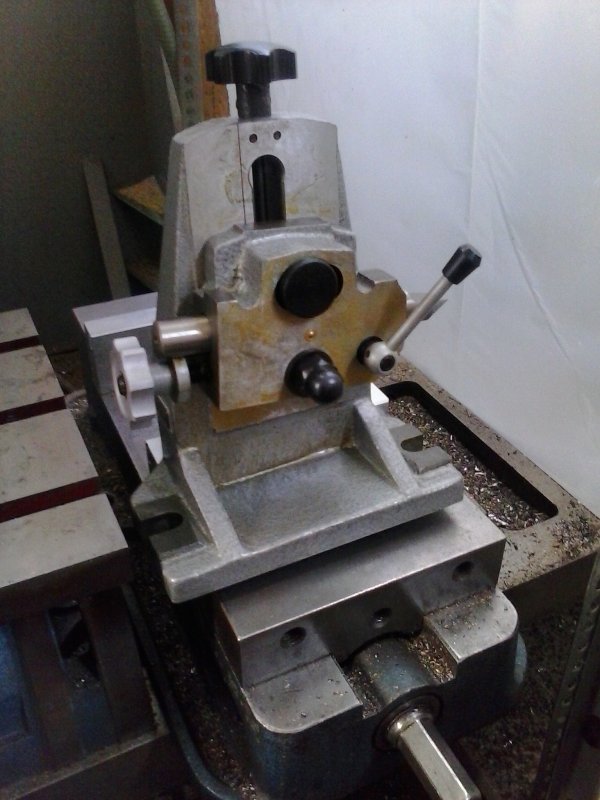
Some more work on getting the 4th axis set up. I was getting misses motion and squeals from the table when commanded. I loosened the 3 socket head screws on the bottom slightly, and that seemed to solve the problem. Here's the setup I used to measure backlash.
Basic technique is to rotate until one vise jaw is parallel to the table; I used a height gauge for that. Then use the DI to establish a zero on a given point of the horizontal jaw, and then move the DI out of the way. Then rotate the table some distance, then back to the start, reposition the DI and see the result. Less than .001 over 90 degrees and then the same over a full rotation of 360.
I did find some issues for future use if I want to use small, short endmills. Since the spindle center is about 4.5" from the side of the casting, the casting will hit the chuck unless its bottom is higher than the chuck body. It can also have a problem in Z with a short endmill.
-
05-16-2015, 12:48 AM #18
Registered
- Join Date
- Mar 2011
- Posts
- 805
Re: 4th axis
Thanks. Information is useful....
-
05-17-2015, 06:25 PM #19
Registered
- Join Date
- Dec 2009
- Posts
- 594
Re: 4th axis
Came up with a solution for small parts and small endmills: I have a keyless chuck with a 1/2" straight shank that I will hold in the jaws of the lathe chuck. This will stick out far enough so that the spindle casting won't hit the drill chuck. This will work for stock up to the 1/2" capacity.
-
05-28-2015, 01:23 PM #20
Registered
- Join Date
- Mar 2011
- Posts
- 805
Re: 4th axis
kvom,
following you and saving time .... how did you attach fourth axis with the table? t nuts? do you think i can achieve larger work area by putting fourth axis at the end of table and attach it to table from front? trying to balance the need for larger work area and stable setup. if you can post a picture, it will help.
thx

 Reply With Quote
Similar Threads
-
4th axis rotation on x axis chaging to Y axis in simulation
By vector459 in forum BobCad-CamReplies: 16Last Post: 09-11-2017, 10:31 PM -
Unwinding the rotary axis ( 4 axis rotary axis milling fanuc control)
By diaa beheiry in forum PowerMILLReplies: 1Last Post: 11-17-2015, 07:37 PM -
Looking for distributors of 5 axis, 4 axis and 3 axis cnc router machine
By Anniehu in forum Servo Motors / DrivesReplies: 0Last Post: 08-04-2013, 05:30 AM -
calculating pulse equivlent factor for a rotary axis in place of the x axis
By MARTYSCNC in forum Excitech routersReplies: 1Last Post: 06-23-2013, 05:02 AM -
5-axis, 4-axis, and 3-axis CNC Router manufacturer
By roctech in forum Roctech CNC RoutersReplies: 0Last Post: 05-24-2012, 09:12 AM
