


Hi
I am trying to convert a traditional lathe to CNC. I got my axes working and need to get my spindle setup. I will be using it with Mach3 and want to be able to do single point threading.
Question1:
From the Dynomotio help-file I read that to do that, I need a quadrature encoder. The encoder will be configured to an axis, that implies to me that the spindle must be driven by an axis and not by an output. This means an on/of spindle with gears can not be used. Or how can it be achieved without it?
Question 2:
Ok, I wanted to install a frequency inverter anyways. What I guess that if an encoder is connected to a step dir signal as an axis there will be some PID controlling on it. I have not read of any possibility to enable / disable any controlling.
And here it gets complicated for me because of the different gear ratios that come into play with different impulse settings.
my setup:
1. a Motor driven by an VFD Impulses 0-50Hz -> 0-2840 RPM
2. different gearsets between motor and spindle
3. Spindle with a 13 tooth sprocket used as a pickup for the quadrature encoder resulting in 13 imp/rev.
I don't really have a need for controlling the spindle speed because the VFD will be doing it already good enough through sensorless feedback.
How can i make this thin running?
Thanks for your help!
Leo
Thread: Lathe Spindle setup
Results 1 to 7 of 7
-
03-02-2014, 09:37 PM #1
 Registered
- Join Date
- Oct 2007
- Posts
- 35
 Lathe Spindle setup
-
03-03-2014, 09:44 PM #2
 Junior Member
- Join Date
- May 2006
- Posts
- 4050
Hi delcon,
To do single point threading a quadrature encoder on the spindle is normally required. An Axis Channel set for encoder input is required to get an encoder position into KFLOP. That does not mean that the Spindle needs to be controlled by the Axis Channel.
You should be ok with manually controlling the speed.
I don't understand Question #2.
The first step would be to get the Spindle encoder connected to KFLOP. It isn't clear whether your 13 tooth sprocket is really putting out quadrature. Quadrature requires two signals usually called A and B that are 90 degrees (1/4 tooth) out of phase. Not just a single sensor outputting pulses. Do you know what you have? See also here.
It isn't clear what you mean by Impulses 0-50Hz. Is that a PWM signal? Can it be higher frequency? The slowest PWM signal KFLOP has is 254Hz.
RegardsTK
http://dynomotion.com
-
03-05-2014, 03:48 PM #3
Registered
- Join Date
- Oct 2007
- Posts
- 35
Hi tom
Thank you for your explanations. If I want to configure an axis without any output and all the available channels are already taken, what would I write in the config file?
To my question #2:
Thank you for explaining that a true encoder is needed. I thought some square wave picked up from a sprocket would be enough. I thought that because when I configure encoder one of the inputs are grayed out.
So how would I connect the two line encoder?
Regards
-
03-05-2014, 05:08 PM #4
Junior Member
- Join Date
- May 2006
- Posts
- 4050
Hi delcon,
I'm not sure I understand. Are you really using all 8 available channels already? If not just use the next one? Configure the new Axis in KMotion.exe then use the C Code->ClipBoard button to create the C code for you whenever you need it. All that matters is the Input Mode, Input Channel 0, and Input Gain 0 as the axis channel will never be enabled.If I want to configure an axis without any output and all the available channels are already taken, what would I write in the config file?
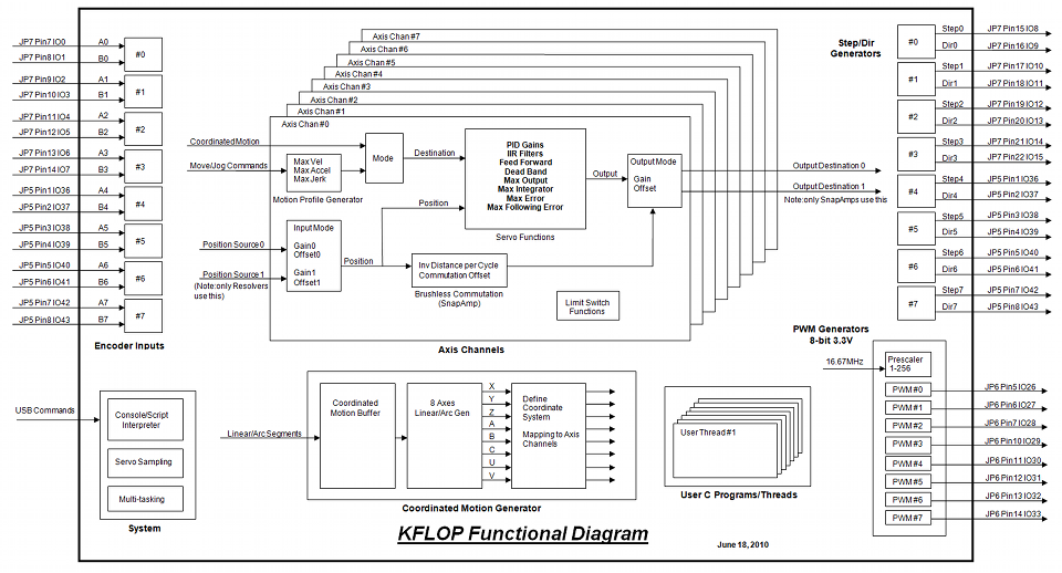
This is a common source of confusion. I suppose because some systems configure input IO or pins (like Mach3). But in KFLOP the "Input Device Channel" is configured. You can basically think of an Encoder Counter as a physical hardware device that is hard wired to some particular IO pins. You are selecting which Device to be used. Some Input Modes require two input devices but with Encoder Input Mode you only need to specify one so the other is grayed out to make this clear. This Functional Diagram may help:So how would I connect the two line encoder?
KFLOP doesn't have any hardware pulse counters (only quadrature up/downcounters), but your pulses are probably slow enough that you could just count them in software. Assuming 3000RPM Max and 50% duty cycle on the sensor, the sensor input should change about every:
60 / (3000 x 13 x 2) = 796us
KFLOP User C programs are guaranteed to execute every 180us. Here is a C Program that you could try if you can't add the B channel to your encoder:
RegardsCode:#include "KMotionDef.h" main() { int last=0; for (;;) { WaitNextTimeSlice(); if (ReadBit(4) != last) // input change? { ch2->Position++; // count last=1-last; } } }TK
http://dynomotion.com
-
03-05-2014, 09:05 PM #5
Registered
- Join Date
- Oct 2007
- Posts
- 35
Hi Tom
Thank your for your explanations. The Diagram made it very clear to me.
Of course I do not run out of Axis, only of generators because the hardwiring.
The user program is also a good solution! I will evaluate these two. What comes in to my mind when I look at the user program:
couldn't possibly lead the consecutive count of ch2 to a stack overflow at one time?
If I define an additional axis for the spindle, do I have to define it after the "DefineCoordSystem" so I does not get counted as an motion axis?
I might have some additional questions later on.
Best regards.
-
03-06-2014, 12:51 AM #6
Junior Member
- Join Date
- May 2006
- Posts
- 4050
Hi delcon,
The stack isn't really involved, but if you are thinking about a Position Register Overflow it won't happen in your lifetime. ch2->Position is a 64-bit floating point variable (52 bits of resolution: 2^52 = 4,503,599,627,370,496)What comes in to my mind when I look at the user program:
couldn't possibly lead the consecutive count of ch2 to a stack overflow at one time?
Do not include the Spindle axis when defining the coordinated motion axes. You can put the call to DefineCoordSystem anywhere. It just needs to be executed before GCode executes.If I define an additional axis for the spindle, do I have to define it after the "DefineCoordSystem" so I does not get counted as an motion axis?
RegardsTK
http://dynomotion.com
-
03-06-2014, 05:12 PM #7
Registered
- Join Date
- Oct 2007
- Posts
- 35
Hi Tom
Thank your for your explanaitions.
Best Regards

 Reply With Quote
Similar Threads
-
CNC Lathe setup
By mroy0404 in forum Mazak, Mitsubishi, MazatrolReplies: 5Last Post: 06-20-2016, 07:29 PM -
Add a Setup to Lathe
By fidia in forum BobCad-CamReplies: 8Last Post: 12-26-2013, 10:52 AM -
D&M 5 Lathe setup
By afaiello in forum Mini LatheReplies: 0Last Post: 04-22-2009, 11:43 PM -
Old lathe spindle setup
By PIngels in forum Uncategorised MetalWorking MachinesReplies: 14Last Post: 12-06-2006, 05:15 PM
