


Nope haven't seen any for sale, email me, I could be persuaded to make a couple we just have to determine which one you'd need.
Hoss
Thread: Andrew's G07040 build
Results 1 to 20 of 241
Hybrid View
-
04-16-2013, 05:36 PM #1
 Member
- Join Date
- Apr 2006
- Posts
- 8159
http://www.hossmachine.info - Gosh, you've... really got some nice toys here. - Roy Batty -- http://www.g0704.com - http://www.bf20.com - http://www.g0602.com
-
05-06-2013, 04:45 PM #2
Registered
- Join Date
- Sep 2012
- Posts
- 323
It's been a little while!
Made a little progress on my build. I had a baby sitter to take my kids for the morning and was able to take apart the machine.
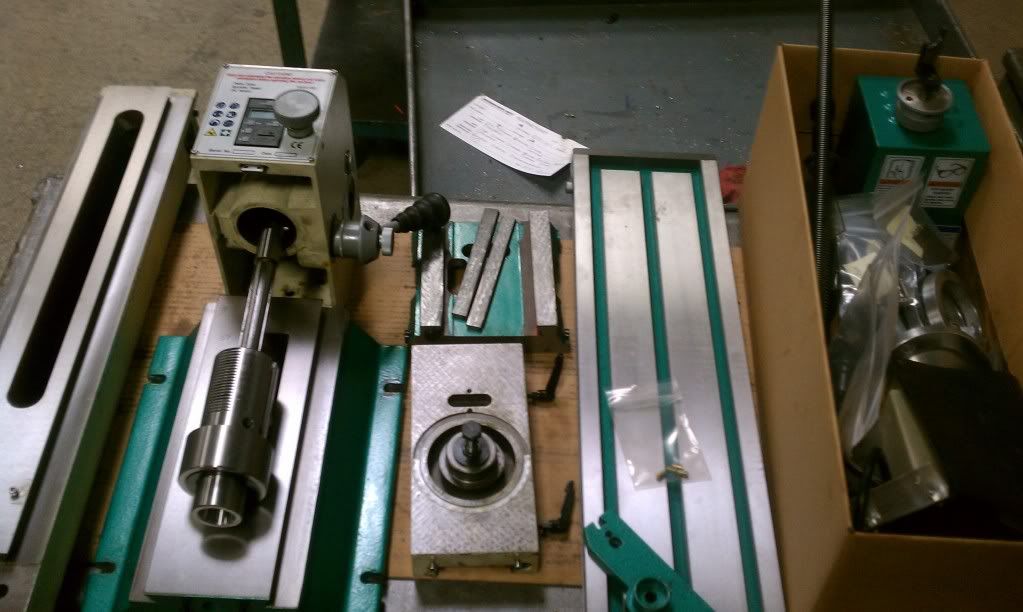
Also got some pulleys and a belt from McMaster for the tread mill conversion.
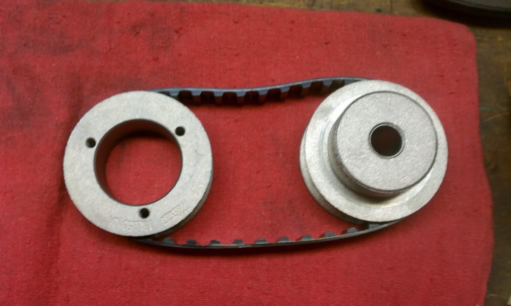
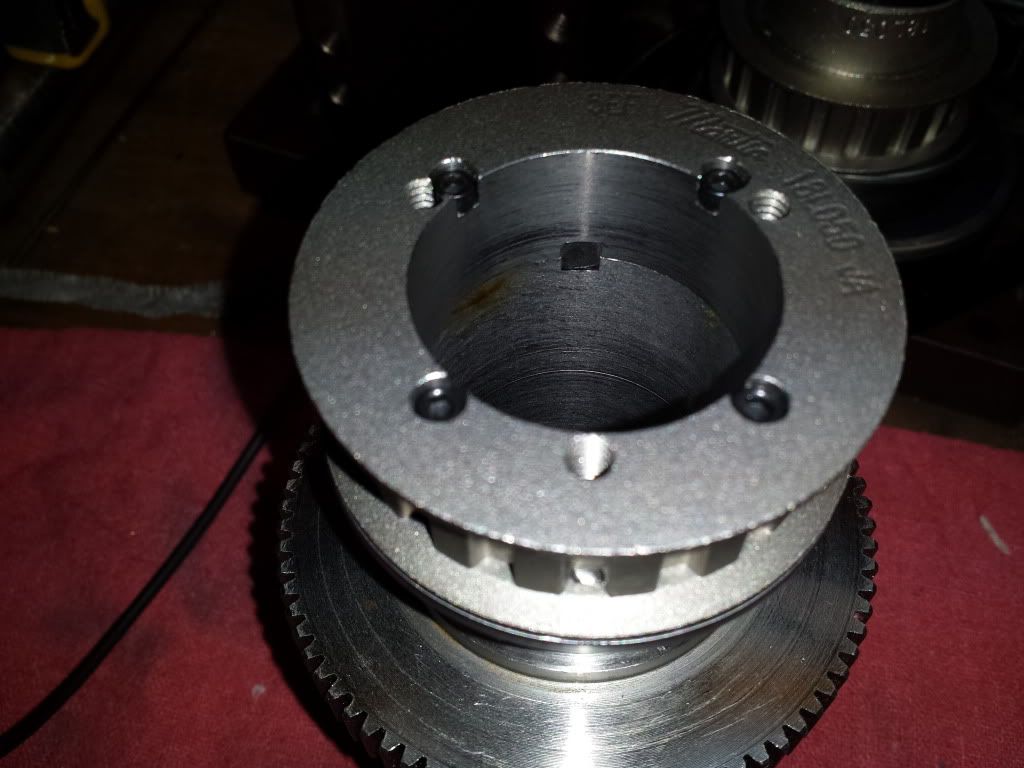
I want to mount the one with the larger opening on the spindle side.
Thinking of cutting a step into the lower part of the pulley to set it on and then put a few screws from the top to hold it there. Looks like I'd need to use some 6-32's and I'm not sure how well it will hold up.
Has anyone gone this route and willing share their work?
Andrew
-
05-07-2013, 02:29 PM #3
Registered
- Join Date
- Sep 2012
- Posts
- 323
I think I got it worked out. I'm going to mill a keyway slot through where the screw go for the RPM pick up. Then I'll counter bore the pulley to seat it on the assembly and cut slots for the key as well. Then put (4) 6-32 screws in to hold it down.
So c'bore to locate, key to lock, screws to hold.
Should work right?")
Andrew
-
05-20-2013, 06:18 PM #4
Registered
- Join Date
- Sep 2012
- Posts
- 323
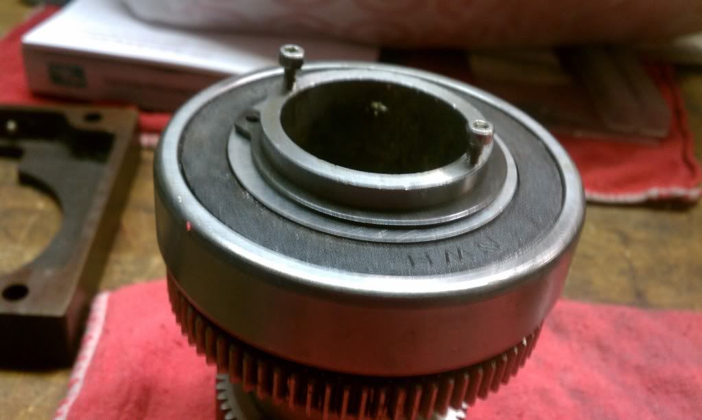
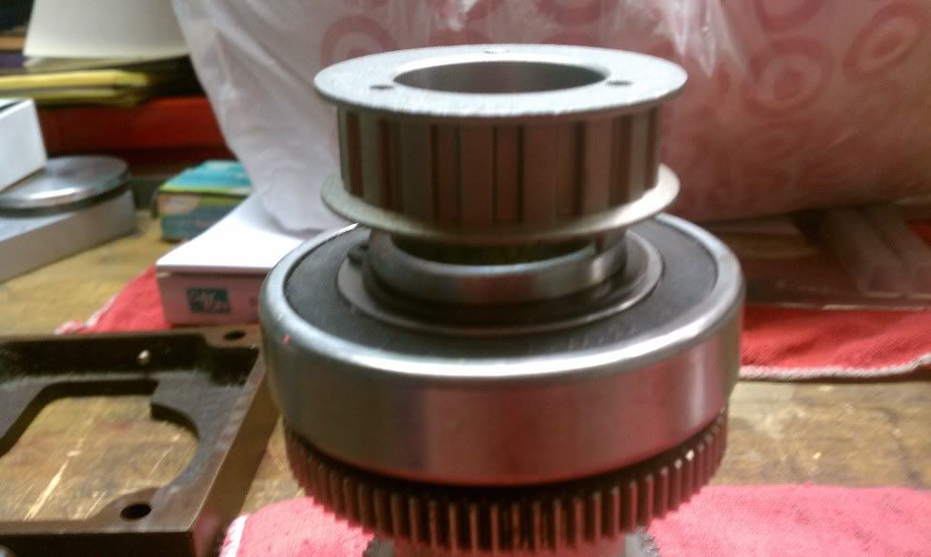
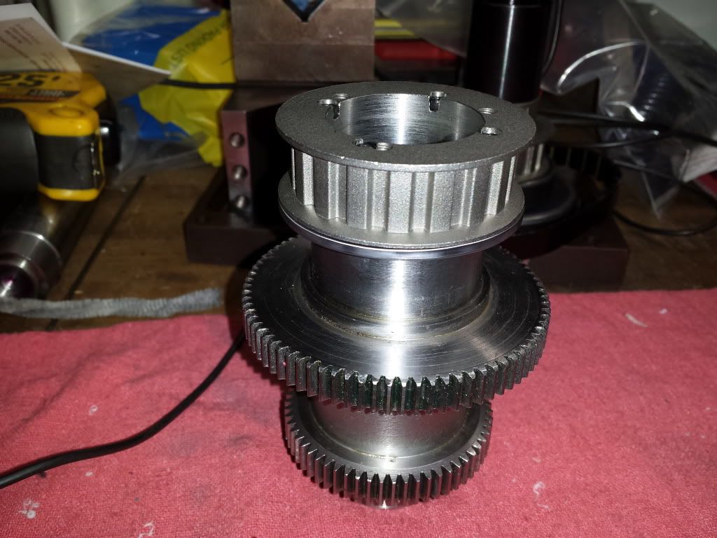
Had a little time last week to machine the pulley and the quill to mount it.
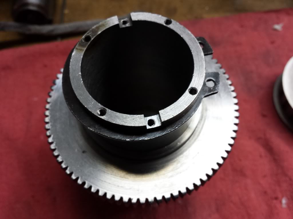
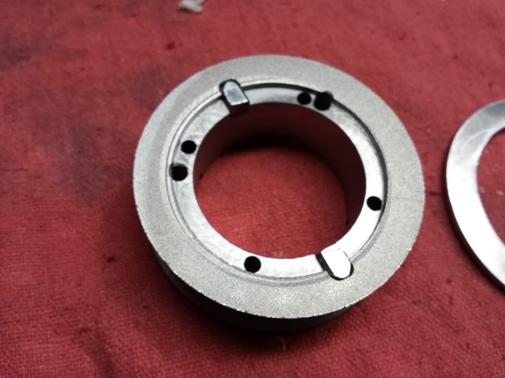
Ran into a few problems along the way. While inserting the keys into the pulley I managed to knock off the the lower keeper on the pulley! Looks like its not a solid piece and the lip I machined must have took out most of the bonding area. So I made a shim to go in between the pulley and the snap ring.
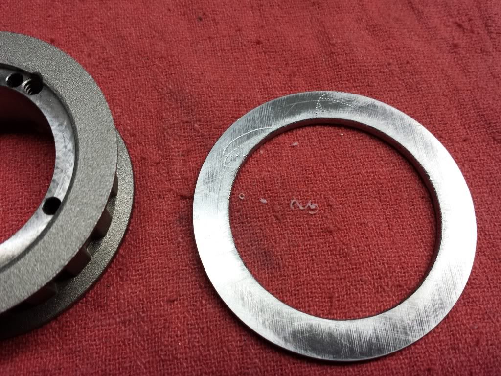
It came up a little thin so I turned it into a wavey washer with a press :idea:
I also managed to break a 4-40 tap in the quill. Lucky for me we have an ED bore machine at work and it took care of the little bastard!
If I was to do it again I would go with a bigger diameter pulley. I went with what I did in case I wanted to get more RPM's down the road.
If anyone wants cad on this I have a few files I can clean up and post.
Andrew
-
08-21-2013, 06:26 PM #5
Registered
- Join Date
- Mar 2013
- Posts
- 124
Question, I understand now about keeping the load off the spindle bearings. Makes perfect sense.
However... How is the drawbar supposed to be able to spin freely in these designs? Does the entire stack of washers + drawbar spin and is there a bearing then in the "lifting plate" below the belvilles?
-
08-21-2013, 06:53 PM #6
Registered
- Join Date
- Sep 2012
- Posts
- 323
There will be a plate that will sit against the risers for the motor mount. It will have clearance around the spindle and will have a .050~.100" gap between a "top hat" and the plate. The disc springs will sit above the top hat. and there will be a gap above the drawbar so the lever doesn't touch. The air cylinder fires and pushes the lever, which in turn also pulls up on the plate and compresses the disc springs. Thats also why the shoulder bolts are used with a spring to keep the plate down when the spindle is turning. Originally Posted by Topdecking

My designs don't show most of that, I was just using it mostly to figure out spacing and how much movement I would get at the spindle end of the lever. This should give me 4X the cylinders pressure and half its travel at the spindle end of the lever
Hope that make a little sence
Andrew

 Reply With Quote


Similar Threads
-
Andrew's G0704 CNC Conversion
By andrew2085 in forum Benchtop MachinesReplies: 12Last Post: 01-21-2013, 06:04 PM -
Mint's Build Aluminum/Steel Build thread.
By FreshMint in forum Maintenance DIY DiscussionReplies: 0Last Post: 10-31-2011, 04:18 AM -
Newbie - To build or not to build Router/Plasma Table
By dfranks in forum Waterjet General TopicsReplies: 10Last Post: 04-08-2011, 05:16 AM
