


Good call, thanks StigoeStigoe
You'll probably want a MPG as well for jogging.
Thanks for the info on the standard motor FannBlade and glad you like the log :cheers:Originally Posted by FannBlade

Thread: Graham's Optimum BF20 Build
Results 21 to 40 of 192
-
04-11-2013, 05:38 AM #21
 Registered
- Join Date
- Nov 2012
- Posts
- 220
-
04-14-2013, 10:20 PM #22
Registered
- Join Date
- Apr 2013
- Posts
- 20
Do you happen to have any pictures of how the ways looked before lapping? I'm comfortable scraping ways (restoring old woodworking machinery teaches odd skills), but hoped to avoid doing such by going with an Optimum mill since it seems their QC is better than the other importers. I'm considering an Optimum BF30, but am not sure it's worth the premium over a PM-30MV. If the build quality is no better than the other mills being imported and requires as much work to get to what I consider a useable state then it's certainly not worth the premium.
Thanks. Clean looking build so far. :-)
-
04-15-2013, 03:14 AM #23
Gold Member
- Join Date
- May 2005
- Posts
- 3920
Well every user is different, but I highly suggest learning to use MDI mode fluently. You will however need some manual controls simply for safety. Originally Posted by gcofieldd
An E-Stop button, one or more is an absolute requirement. DO NOT skimp on the push button, make sure it is of industrial quality. I've seen 50 year old woman break an E-Stop button and that wasn't even a panic situation. If you want to be compliant, coming out of E-Stop requires a separate operation, in other words the machine can't come back on if the E-Stop is released. Sadly it is hard to tell the good ones (E-Stop Pushbuttons) from the bad ones, it even varies significantly within manufactures lineups.If I do make a control panel these are the functions I think I need:
E-Stop
Again it depends upon your intended use but a cycle start button can be very handy. It is especially useful if you run a lot of the same parts through the machine.Cycle Start
If you mean a manual feed rate pot this may have some potential but again it depends upon the user.Cycle Stop/Pause
Spindle Manual/Auto
Spindle Start/Stop
Spindle Forward/Reverse
Variable Speed Pot
If you think you have a need for a lockout (little kids) or this is a machine for commercial use, put a disconnect switch on the machine so that it can be powered down and locked out 100%.Coolant On/Off/Auto
Key Lockout
Not everything needs to run though your CNC controller.Maybe a light switch and tool change button...
Note: the things I didn't comment on are probably a waste of time. A good GUI should make access to most of hose features simple. So you just end up wasting money and I/O. Things like a manual feed rate control are a but different, some would see such an input as a waste others wouldn't.
The real trick with control boxes is clean wiring and a space to expand into so that supporting new ideas or features is easy. That applies to your operator panel also.Here are the pics deleted)
Currently the X and Y axis ballscrews are out for machining, I am working on the Z axis, I am working on the control box and possbly the control panel.
-
04-17-2013, 10:41 PM #24
Registered
- Join Date
- Nov 2012
- Posts
- 220
Wizard thanks for taking the time to write that reply that was very helpful!

-
04-17-2013, 11:52 PM #25
Registered
- Join Date
- Nov 2012
- Posts
- 220
Hey UScompact, Originally Posted by USPcompact
I only have one picture of before I lapped, but you can't tell much from it.
The only plus I can think of for the Optimum BF30 is that it uses a brushless DC motor for the spindle.
The Optimum/Toptech BF30 is 3299.99 vs MD001 which is 2499.99. The PM-30LV is 1895.00 with free freight--that is hard to beat.
I think there is a very marginal quality difference, but it is not worth the price for the Optimum. I would say don't make the same mistake I did. I wish I had gotten the MD001 or the PM-30LV.
-
04-18-2013, 12:03 AM #26
Registered
- Join Date
- Apr 2013
- Posts
- 20
Thanks much. That was exactly the info I was looking for. Originally Posted by gcofieldd
-
05-11-2013, 03:14 AM #27
Registered
- Join Date
- Nov 2012
- Posts
- 220
Motor Replacement
I have been searching for a motor replacement for my BF20 for over a year now and I think I finally found something today. I wanted something small enough that I could mount the motor and a pneumatic draw bar without having to put a spacer between the head of the mill and the z-axis carriage. Also, for some reason I did not want to use a tread mill motor.
I found a 230 VAC 3 phase motor that is 4.42 inch square. The only reason I have not jumped on it yet is because I am not sure how the torque compares to the stock BF20/G0704 motor. The MFG provides a torque curve for the motor.
Here is a link to the motor:
AC & DC Motors, Universal Motors | Groschopp Motors
Here is a link to where you can buy it:
Electromate Industrial Sales
I was hoping someone who knows more than me can take a look and see what you think about the motor.
-
05-12-2013, 10:51 AM #28
Registered
- Join Date
- May 2008
- Posts
- 3
Dear gcofieldd and other members hallo,
I have just finished converting my optimum bf 20l spindle upgrade replacing the bearings with angular contact, p4 found on ebay , and accidentally fount your topic discussion. You have make nice work as seen from pictures, keep on.
I like to contribute with my approach on bearing preload. First I replaced MT2 spindle with a new R8 ordered directly to Weiss and received in 5 working days. Replaced because of poor run out performance, Weiss because it is a drop fit change with excellent performance and let me use TTS tool holders. (Both Optimum and Weiss buy spindle assembly outside casting (mill head) from the same foundry, so same internal dimensions).
On preloading and run out performance now, after many disappointing spindle mounting and disassembly (almost 10-15 times) to mill head I laid the complete spindle on the mill table, shaft along table, and clamped it to the table. Then placed a dial indicator to the R8 side of spindle and rotated by hand. Real time readings. When preloading was excess, run out was increasing, when preloading was less, spindle slop was appearing. The area of perfect load on the preload bolt was very narrow, almost a couple of degrees of rotation, and then , when I fastened the 2 securing bolts, this action induced bolt shift to the more preload side. With trial I managed to reduce run out to less than 0.01 mm or 0.005 in. Motion is smooth with no freewheeling nor drag. Next thing I noticed is an increase in run out when I inserted spindle on the head. Run out from 0.01mm jumped to 0.08-0.15mm. Careful inspection of the spindle shaft upper side showed little marks on the multy spline channel sides (made during factory assembly ,apparently) . Removed them easily with hand sandpaper grinding , and run out returned to normal 0.01mm. Now I will brake in and look for heat up.
george
-
05-14-2013, 03:58 AM #29
Registered
- Join Date
- Nov 2012
- Posts
- 220
Most123, thank you for the post and the information about smoothing the burrs on the spindle splines. My spindle has burrs as well and it would have taken me a while to figure that one out.:cheers:
-
05-17-2013, 02:32 PM #30
Registered
- Join Date
- Oct 2011
- Posts
- 40
Hi, those parts look really nice! Originally Posted by gcofieldd
Which kind of Aluminium is this?
Sure it isn't Stainless Steel")
-
05-18-2013, 12:22 AM #31
Registered
- Join Date
- Nov 2012
- Posts
- 220
Thanks Dingenman
The aluminum is 6061-T6511 some variant of 6061.
-
05-18-2013, 05:49 AM #32
Registered
- Join Date
- Nov 2012
- Posts
- 220
I finally got around to doing the three bolt head mod. I used my calipers to scribe a line to mark the center of the holes. I used the edge of the large center hole to guide the calipers. I also took some 320 grit sand paper and used my Dewalt random orbital sander to make a nice even mat finish on the aluminum parts I have had made for the conversion. After that I dropped them off to get black hard anodized. I will post some pics when I get them back.
Attachment 185252
Attachment 185260
Attachment 185254
Attachment 185256
Attachment 185262
Attachment 185258
-
08-07-2013, 04:53 AM #33
Registered
- Join Date
- Nov 2012
- Posts
- 220
It has been a while since I posted any progress. It has been slow going. I have been doing a lot of reading and learning trying to design the control box, but I think I have it pretty much figured out. When I finish the wiring diagram I will post it up. I took a break from that to work out some of the smaller mechanical details of the parts I am designing for the conversion. I think I just have five small parts left to do, which are sheet metal covers for the steppers and a mount for the x-axis limit switch. I thought I would post some pics of the 3D model with the finished parts showing in the model. I am at the point where I am going to start moding the saddle and z-axis carriage for the oil ways and after that I can start assembling—probably three months from now. Anyway here are the pics of the model.
Attachment 195150
Attachment 195152
Attachment 195154
Attachment 195156
Attachment 195158
Attachment 195160
Attachment 195162
Attachment 195164
-
08-07-2013, 08:06 AM #34
Registered
- Join Date
- May 2008
- Posts
- 3
 stepper cover
dear graham
for stepper motor covers, i prefer to use transparent plastic over sheet metal.
The cover is only for debris protection, no hard work to be done, and transparency
as real time motion observation, gives a feel of confidence .
I look forward to copy your oil channel project, many photos please.
-
08-10-2013, 06:34 AM #35
Registered
- Join Date
- Nov 2012
- Posts
- 220
Hey most123, I will definitely put up a lot of pictures as I move forward and thanks for the feed back. I am using the stepper covers to mount the feed through bulkhead mount connectors which my cables attach to, so that is why I am using metal covers. I have finished all the design work on the mill components that I need for this phase of the conversion. I will work on the pneumatic draw bar and motor upgrade after I get the mill up and running. Here are a couple of pics with everything on the mill. Originally Posted by most123
-
08-27-2013, 04:14 AM #36
Registered
- Join Date
- Nov 2012
- Posts
- 220
I have been working on laying out the control box. Here is a picture of the electrical panel inside the box. The box I am using is 20" x 20". I thought it would be big enough, but things are getting tight in there quick; lesson learned--always get a bigger box...
Attachment 197898
-
09-07-2013, 06:05 AM #37
Registered
- Join Date
- Nov 2012
- Posts
- 220
Making progress!
I thought I would give you guys an update. I got the mill modded to add the oil groves. On the z-axis carriage I drilled three holes from the top (that is where the oil lines hook-up. Then I drilled a hole on each side to intersect with the outer two holes coming from the top. I then drilled holes on the back to tie all the intersecting holes together. This seemed like a clean way to get the z-axis oiled; it also lets me oil the z-axis ball nut. I had to machine the front of the colmn a little higher to accommodate the fitting that will be on the back side of the z-axis carriage. The hole for the fitting is right above where the ball nut mount attaches. I used a similar approach for the saddle. I drilled two holes on the front and back of the saddle and then drilled down from the top to intersect the holes. The oil fittings mount in the three holes in the middle of the saddle where the holes for the ball nut mounts are. The last pic is of the parts I just got from Scott. The parts are my ball nut mounts, z-axis pillow block mount, oil manifolds, and one of the parts for the limit switch system that mounts on the saddle using the existing M6x1 holes. I ran into a little bit of a problem with the ball nuts I got through homeshopcnc.com. The dimensions of the ball nuts do not match the spec sheets they have posted on their website. I have already had the x and y-axis ball nut mounts remade and now I have to have the z-axis ball nut mount remade, which really sucks. In the next couple of weeks I am going to start assembling the mill and building the control box, so things are starting to get exciting
Attachment 199574
Attachment 199576
Attachment 199578
Attachment 199580
Attachment 199582
Attachment 199584
-
09-09-2013, 02:19 AM #38
Registered
- Join Date
- Nov 2012
- Posts
- 220
I have been trying to decide between three different VFD drives and I am having trouble making a decision. I thought I would post this up and see what you guys think. Here are the drives and why I like them. I am leaning towards the KBVF-14 from KB Electronics.
KBVF-14: This drive eliminates inrush on motor start up, has an optional signal isolation module for the control lines, is very simple to setup and control (just like the DC drive Hoss recommends from KB) and is fairly inexpensive at around $144.
KBVF-14 Adjustable Frequency AC Drive
The next two drives are from Delta (Welcome to Delta Electronics, Inc. - Automotive Products) and are very similar (not sure what the difference is--anyone know?).
VFD007EL11A: This drive comes with a key pad, has an included din rail mounting provision, is more complicated than the KBVF-14 and does not have the key words “sensor less vector drive”. It costs around $200. Here is the description from the website:
The VFD-EL series is multiple function new generation micro type AC drive. It has built in EMI filter, RFI switch, easy DC bus sharing for side-by-side installation, high precision current detection, overload protection, and a built In keypad.
‧Output frequency: 0.1 ~ 600Hz
‧3 points adjustable V/f curve
‧Built-in PID feedback control
‧RFI-switch for IT mains
‧Built-in EMI filter (for models 230V 1-phase and 460V 3-phase)
‧Use RS-485 communication interface (RJ-45) with Modbus protocol
‧Optional communication modules for multiple communication protocols, such as Profibus, DeviceNet, LonWorks and CANopen
‧Complete protection function
VFD007E11A: This drive does not come with a key pad, but seems to be the type of drive everyone is using. It costs around $220. Here is the description from the website:
Sensorless Vector AC Micro Drive. The VFD-E series represent Delta Electronics low horsepower, constant torque, IP20 rated Drive. Modular in design with flexible extension cards and a built-in PLC function, the E drive offers the ability to write and to execute simple Ladder Logic programs. This state-of-the-art series meets a full range of application requirements.
‧Output frequency: 0.1~600Hz
‧Modular & compact design
‧Built-in PLC function
‧Built-in EMI filter (230V 1 phase / 460V 3 phase)
‧Optional Fieldbus Modules (DeviceNet, Profibus, LonWorks and
CANopen)
‧RFI-switch for mains
‧Easy DC BUS sharing
‧Flexible extension
‧Complete Protection
Any thoughts would be appreciated.
Thanks
Graham
-
09-14-2013, 02:25 PM #39
Member
- Join Date
- Oct 2008
- Posts
- 1641
Nice looking mounts. I wish my first machine would have been a BF20 style machine instead of the SX3. The SX3 is not bad but I had to overcome several issues and I wasted a lot of money with all the extra bells and whistles that don't work well with CNC.
On the drive, I'm not sure. I had a different goal and went with a 3 phase AC motor and VFD. I can see advantages to both, the DC style and the AC. I think over all the DC system is much less expensive than going AC and it probably has better low end torque although my AC sensorless vector drive does pretty darn good on the lathe and the mill. I use a 2 speed belt drive that is pretty much 1:2 or 2:1 and rarely use the low speed unless I tapping large holes. Hoss and others show how well the DC systems do to so it's a toss up.
You are most likely aware of this, but a lesson I learned that might be beneficial to you, is to make sure "all" mounting points are machined square to the ways. For example, the front of the machine where your Y axis mount goes, make sure it is flat, and perpendicular to the Y axis ways. I found that there is some filler material used to pretty up the machine and those surfaces, even some of the machined areas are not that square. Even a small variance will introduce an error and cause your ball screws to flex or bind due to misalignment. Another place is the ball nut mounts. Just because it's a machined flat area doesn't mean it was machined on the same plane from the factory. I often wonder what process they use that would allow some of that stuff to be as far off as it can be.
-
09-14-2013, 02:31 PM #40
Member
- Join Date
- Oct 2008
- Posts
- 1641
Looking good.
Yes, I'm using a 24x24x8" size enclosure and it didn't take long to fill it up to the max either! I like the fact your modeling yours. Wait till you add all the wiring!
A lot of the space in mine is used by cable trays/ducts in order to keep the wires neat and to provide separation. I have inputs, outputs, AC, DC, and Servo Drive wires all separated and routed away from each other. That was pretty challenging in itself.
Originally Posted by gcofieldd

 Reply With Quote
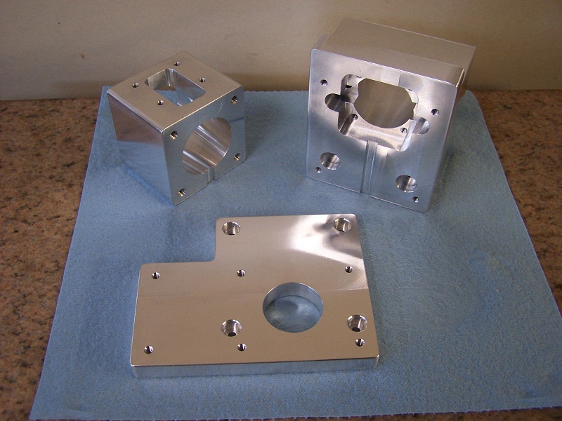
Similar Threads
-
my converted optimum bf20 cnc for sale
By 3barboost in forum South Africa Club HouseReplies: 0Last Post: 03-07-2014, 08:39 PM -
Yet another BF20 build by a noob
By crclark in forum Benchtop MachinesReplies: 21Last Post: 02-27-2012, 09:40 PM -
Optimum BF20 G0704 Conversion
By Winnfield in forum Benchtop MachinesReplies: 0Last Post: 08-07-2011, 12:16 AM -
Sieg KX3 or Optimum BF20? Need advice, please.
By anlmat in forum Uncategorised MetalWorking MachinesReplies: 2Last Post: 01-30-2011, 10:21 AM -
BF20 BALLSCREW OPTIMUM
By dfv in forum Uncategorised MetalWorking MachinesReplies: 0Last Post: 04-16-2010, 07:26 PM
