


All,
I've finished the coolant system upgrade testing this evening and am in the process of uploading a video to YouTube. This process has been fairly slow coming, starting with testing of the stock system, making minor improvements to it, researching what could be done to improve the system inexpensively and executing, which took me about a week of evenings.
To summarize, the stock Tormach flood coolant system flows between 33 and 50 GPH. The new system I've put in place flows 295 GPH. The cost of the full enclosure and the coolant system upgrade was about $235 (which doesn't include a handful of hose clamps and the plastic storage container I used for the reservoir). There's a simple change you can make that will increase the flow of the Tormach OEM system to about 100 GPH.
Last summer I realized you can do things that impede the flow of the Tormach OEM coolant system unintentionally and that got me thinking about ways to improve the system. I cut a part one afternoon with flood coolant and thought the system may be clogged because the flow was so poor. As it turns out, I had tightened the fitting from the coolant supply hose to the black steel pipe too tightly which resulted in the silicone O-ring extruding into the flow path of the coolant. I figured that out when I flow tested the Tormach nozzle repeatedly, removing one part of the nozzle at a time until I figured out what was happening. I attached a picture showing the O-ring extruded into the flow path compared to its free state.
An easy improvement in coolant flow is simply disconnecting the OEM coolant supply hose from the nozzle and using the flow out the end of the hose. This will increase flow from a maximum of 50 GPH to about 100 GPH. I just used zip ties to attach the hose to the nozzle so I could aim it. I've attached a picture below.
I recently had the time to build a full enclosure and a new flood coolant system with three nozzles. The enclosure is PVC pipe and shower curtains. The pump is a Superior Pump 1/4 HP 91250 and I've added three nozzles. The video of the build of the enclosure and coolant manifold is here:
Full Enclosure Build and Flood Coolant Upgrade - Tormach PCNC 1100 - YouTube
I completed the flow testing tonight and I'm fairly pleased. Here are flow test results (all values shown are averages from several samples):
OEM configuration: 32.7 GPH
OEM minus flexible nozzle, just surgical tubing: 33.0 GPH
OEM minus shut-off valve and down stream components: 34.4 GPH
OEM minus all except steel pipe: 36.6 GPH
OEM hose only: 101.0 GPH
OEM configuration minus blue silicone O-ring: 50.7 GPH
The coolant flow was obviously restricted by the O-ring. Now for the new configuration:
3 nozzles: 293.1 GPH
1 nozzle: 115.1 GPH
Here's the video about the nozzles, the pump, testing, etc.
Flood Coolant Upgrade and Flow Testing - Tormach PCNC 1100 - YouTube
There are two pictures attached showing the flow comparison as well.
Enjoy!
Results 1 to 20 of 46
Hybrid View
-
01-16-2013, 06:03 AM #1
 Registered
- Join Date
- Dec 2004
- Posts
- 57
Full Enclosure and Coolant System Upgrade
-
01-16-2013, 09:24 AM #2
Registered
- Join Date
- Feb 2007
- Posts
- 1041
Nice job brother ! I used homedepot shower liner under my head and added a bib to the Z bellow, makes life easy !
-
01-16-2013, 11:25 AM #3
Banned
- Join Date
- Jun 2012
- Posts
- 111
Are you doing anything to protect the control panel?
-
01-16-2013, 03:15 PM #4
Registered
- Join Date
- Dec 2004
- Posts
- 57
Yes, and it's shown in the first video if you'd like to see it. The solution was the simple. The shower curtains I installed were too long, so I took the trimmed off bottom section of the shower curtain I used for the front (5 mil thick clear) and covered the front panel and gaps around the doors. Magnets were used to hold the cover in place. It's not cleanly executed, but it should work fine. Originally Posted by sperman

-
01-16-2013, 10:12 PM #5
Registered
- Join Date
- Aug 2009
- Posts
- 294
That's what I have on mine as well. I used magnets from a hard drive to hold a large sheet of plastic in place. The cabinet isn't fully enclosed, but anything that splashes onto the plastic now runs down to the pan instead of splashing onto the pan. My enclosure is also PVC pipe. Originally Posted by anglin
-
01-17-2013, 12:27 AM #6
Registered
- Join Date
- Feb 2006
- Posts
- 1072
Very nice, anglin. I'll probably wrap a couple of your ideas back into my own setup.
Randy
-
01-17-2013, 03:19 AM #7
Member
- Join Date
- Jun 2005
- Posts
- 656
My flow-rate limiter seems to be the chip basket. That clogs up soon enough that coolant doesn't get back into the tank fast enough. I have a real early stand, so maybe they fixed it later on?
-
01-17-2013, 05:16 AM #8
Registered
- Join Date
- Dec 2004
- Posts
- 57
Thanks for the feedback everyone.
Interesting. I've been very curious to see what will happen when I start covering the chip tray with chips and the coolant is more likely to be delayed getting back to the tank. I was planning on making some cuts tonight but didn't get a chance. As I make more videos related to this topic I'll put them here. Originally Posted by shred
Thanks again.
-
03-03-2013, 05:51 PM #9
Registered
- Join Date
- Dec 2004
- Posts
- 57
So, I've had exactly this problem now. The chip basket in the table is getting filled to the point where the coolant is being restricted from returning to the coolant reservoir. The table starts to fill up to the point where just the handles of the chip basket are showing above the coolant. Every once in a while I just reach in with a gloved hand and scoop it out and immediately the table drains. This is a good problem to have, I suppose. I'll redesign/reconfigure the chip basket in the future to avoid this. Originally Posted by anglin
In the meanwhile, here's the first production part I ran using the new flood coolant system and enclosure:
First Part with the New Flood Coolant System - Tormach PCNC 1100 - YouTube
I was thrilled with the results. I haven't seen any evidence of chip recutting at all since the flood coolant upgrade.
-
03-06-2013, 03:19 AM #10dbrija GuestNope. Still a limiting factor. In my experience anyway... Originally Posted by shred
-
03-10-2013, 05:53 AM #11
Registered
- Join Date
- Dec 2004
- Posts
- 57
I threw together a quick video showing the clogged coolant drain screen to show the degree to which this can be a problem. Originally Posted by dbrija
Tormach PCNC 1100 - Clogged Chip Tray - YouTube
-
04-15-2013, 12:37 AM #12
Registered
- Join Date
- Mar 2013
- Posts
- 91
You must have tried pretty hard to clog the stock 3"x 9" Tormach drain. I have yet to clog the stock tormach 3"x 9" drain with the new 1200 GPH pump.
Don Clement
-
04-15-2013, 12:57 AM #13
Member
- Join Date
- Jun 2005
- Posts
- 656
FWIW, my old and tired drain basket clogs quite quickly now with the stock pump and lots of aluminum removal. Replacing the screen helps but doesn't entirely solve the problem.
-
04-15-2013, 02:26 AM #14
Registered
- Join Date
- Dec 2004
- Posts
- 57
Not really. When it is backing up like that it happens when the basket is filled to the top. It clogs about every third one of these: Originally Posted by takewhatyoulike
Tormach PCNC 1100 - Coilover Suspension Spring Perch Manufacture - YouTube
I think shred's post pointed out the issue. Even when I scoop out the screen, it doesn't get clean because there is so much chip debris stuck in the screen.Christopher Anglin
www.mc2racing.com
-
01-19-2013, 11:12 PM #15
Registered
- Join Date
- Dec 2004
- Posts
- 57
I conducted more coolant flow testing today. I figured I'd post the the results of the new configurations I tried while the video is processing.
I was looking at the OEM Tormach hose assembly and realized that if I took the shut-off valve out of the hose assembly I'd have essentially a 1/2" version of the 1/4" hoses I installed the other day. I put the pieces together and attached it to the coolant manifold. The flow rate improved so dramatically that I ended performing a few other comparison test.
I also tested the 1/2" hose with straight tip and 1/4" 90° nozzles as well as a 1/4" nozzle and straight tip. Here are all the result (new results italic).
OEM system (all Tormach-supplied hardware and pump):
1/2" hose, OEM configuration: 32.7 GPH
1/2" hose, OEM configuration minus blue silicone O-ring: 50.7 GPH
OEM metal hose only: 101.0 GPH
My system with 1/4 hp pump and PVC manifold:
Three 1/4" hoses, 90° tip: 293.1 GPH
One 1/4" hose, 90° tip: 115.1 GPH
One 1/4" hose, straight tip: 127.1 GPH
One 1/2" hose, straight tip: 239.6 GPH
One 1/2" hose, straight tip plus two 1/4" hoses with 90° tip: 369 GPH
There are a few pieces of information worth taking away from the test results (speaking for myself, of course; this may have no value to you or your configuration).
First, switching the 1/4" hose from a 90° tip increases flow from 115 GPH to 127 GPH. That means a switching from a straight nozzle to a 90° nozzle will reduce flow out that hose by 10%, which is not insignificant. In theory, switching the 1/4" hose with 90° nozzles to straight nozzles will increase flow from 293 GPH to 322 GPH.
Second, a single 1/2" straight nozzle flows 82% of what three 1/4" hoses with 90° nozzles.
Third, using the flow ratio of one 1/4" 90° hose against three 1/4" 90° hoses, it is implied (assuming the pump flow rates are constant) that switching to three 1/2" hoses with straight nozzles would provide a flow rate of 500 GPH.
One thing this doesn't point out is the quality of the stream of coolant coming out of the nozzle. At these flow rates, the 90° nozzle has a very disrupted flow, whereas the straight nozzles have a smoother flow. More coolant hits the target and is sprayed around less. I'll see if I can include that detail in the video.
I'll have the video up shortly.
-
04-14-2013, 05:34 AM #16
Registered
- Join Date
- Dec 2004
- Posts
- 57
Scaling the values like this worked very well I completed the test of three 1/2" Loc-Line hoses with straight nozzles this evening. The average flow rate over nine samples was 505 GPH. With straight nozzles on the ends of the hoses instead of 90° nozzles, the flow stream is much smoother. I've attached a picture for comparison. There will be video later, as well. Originally Posted by anglin
My system with 1/4 hp pump and PVC manifold:
Three 1/4" hoses, 90° tip: 293.1 GPH
One 1/4" hose, 90° tip: 115.1 GPH
One 1/4" hose, straight tip: 127.1 GPH
One 1/2" hose, straight tip: 239.6 GPH
One 1/2" hose, straight tip plus two 1/4" hoses with 90° tip: 369 GPH
Three 1/2" hoses, straight tip: 505.1 GPH
I measured my garden hose last summer and it took 18 seconds to put two gallons in a bucket. I was putting two gallons in a bucket in 14 seconds with the coolant system. It's worth mentioning that my return system is thoroughly overwhelmed by this amount of coolant. Practically, I'll have to add another coolant return from the tray under the chip screen in the Tormach stand or else this amount of flow is totally unusable.Christopher Anglin
www.mc2racing.com
-
04-14-2013, 12:44 PM #17
Registered
- Join Date
- Jul 2006
- Posts
- 367
Hello Christopher, Although not a Tormach, I basically converted my mill's coolant system, in the same way as you have. I also had issues with the the amount of coolant overwhelming the original drain system. Here's a couple things I did .........
I eliminated any type of screening/chip catching in the pan area and moved that function externally. Basically, let the chips flow out with the coolant.
Here's a pic of my tank... (don't laugh, my grandkids out grew the toy box and I just repurposed it)
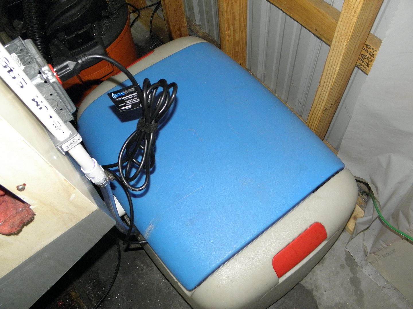
I also repurposed the original coolant tank. It acts as my chip collector/strainer. Here is a shot of the original tank inside the toy box (with 20 gallons of coolant). I'm probably going to drill some holes in the original tank to facilitate the overflow. I just didn't do it yet, till I have seen how the system works.
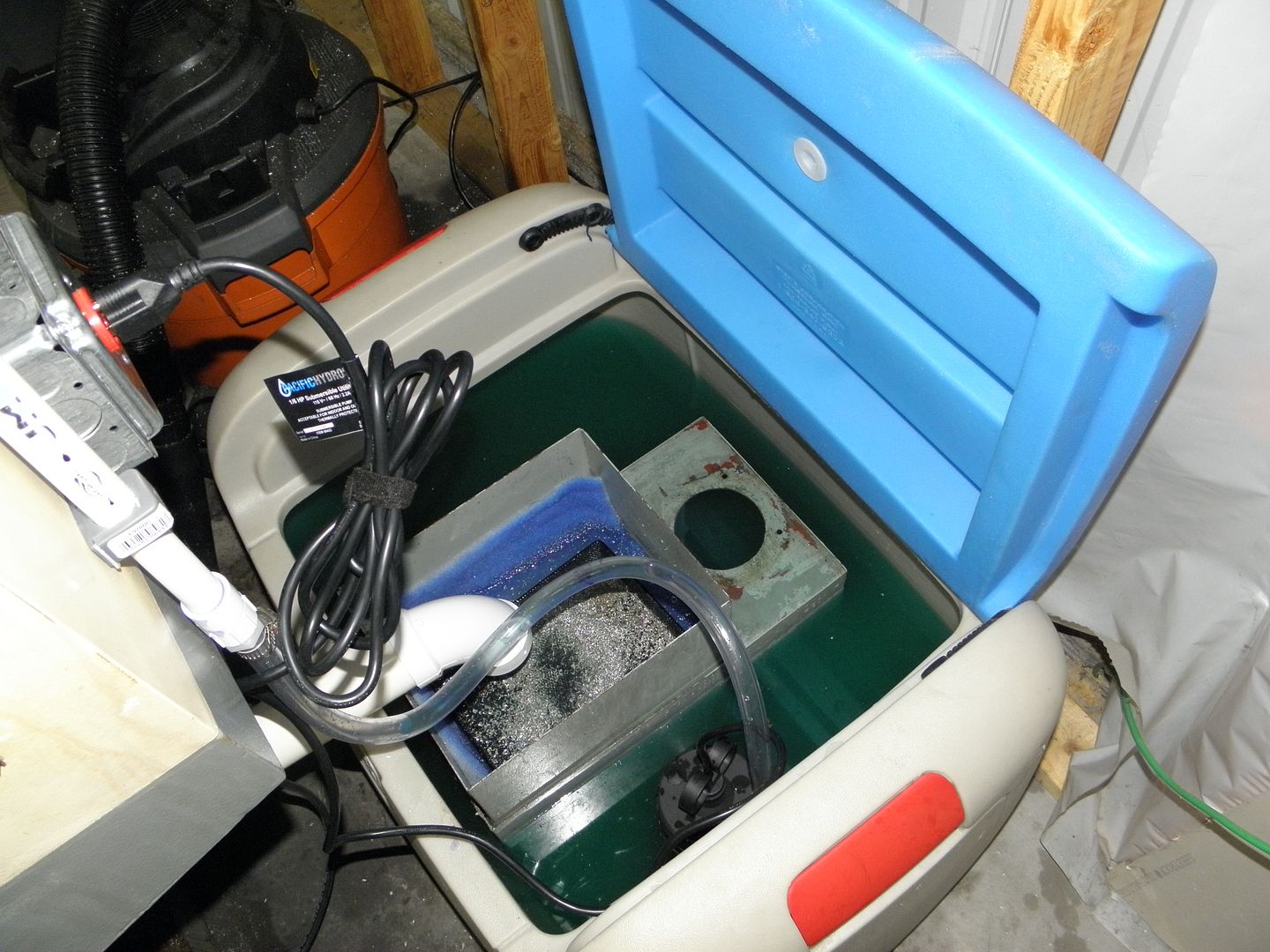
I found that cleaning out the chips is so much easier this way.
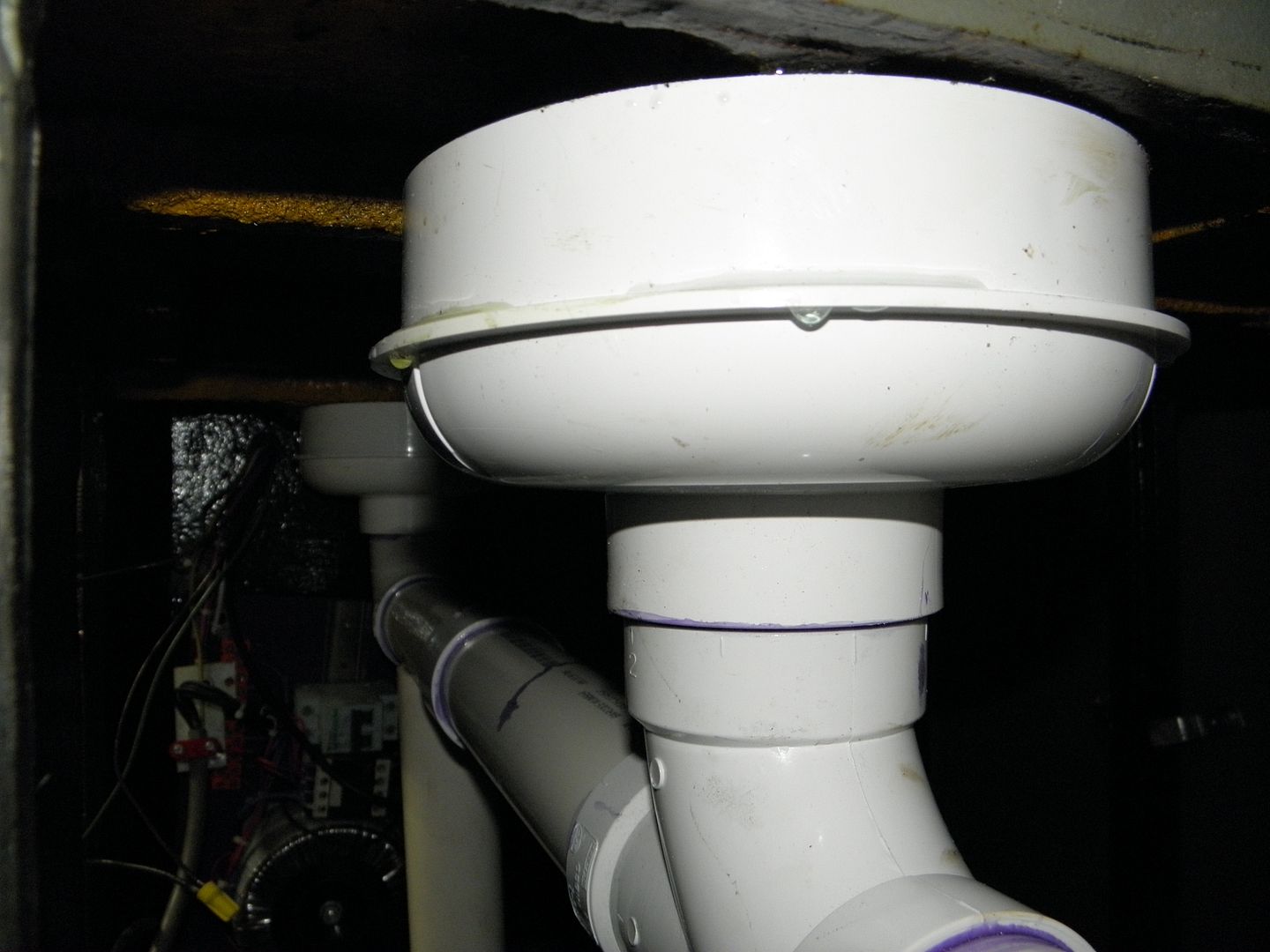
In my situation, I also installed a second drain opposite to the old one. now I have drains on the left and right sides of the mill.
Lastly, since you installed a nice pump, you may want to install one of these to help clean the machine....
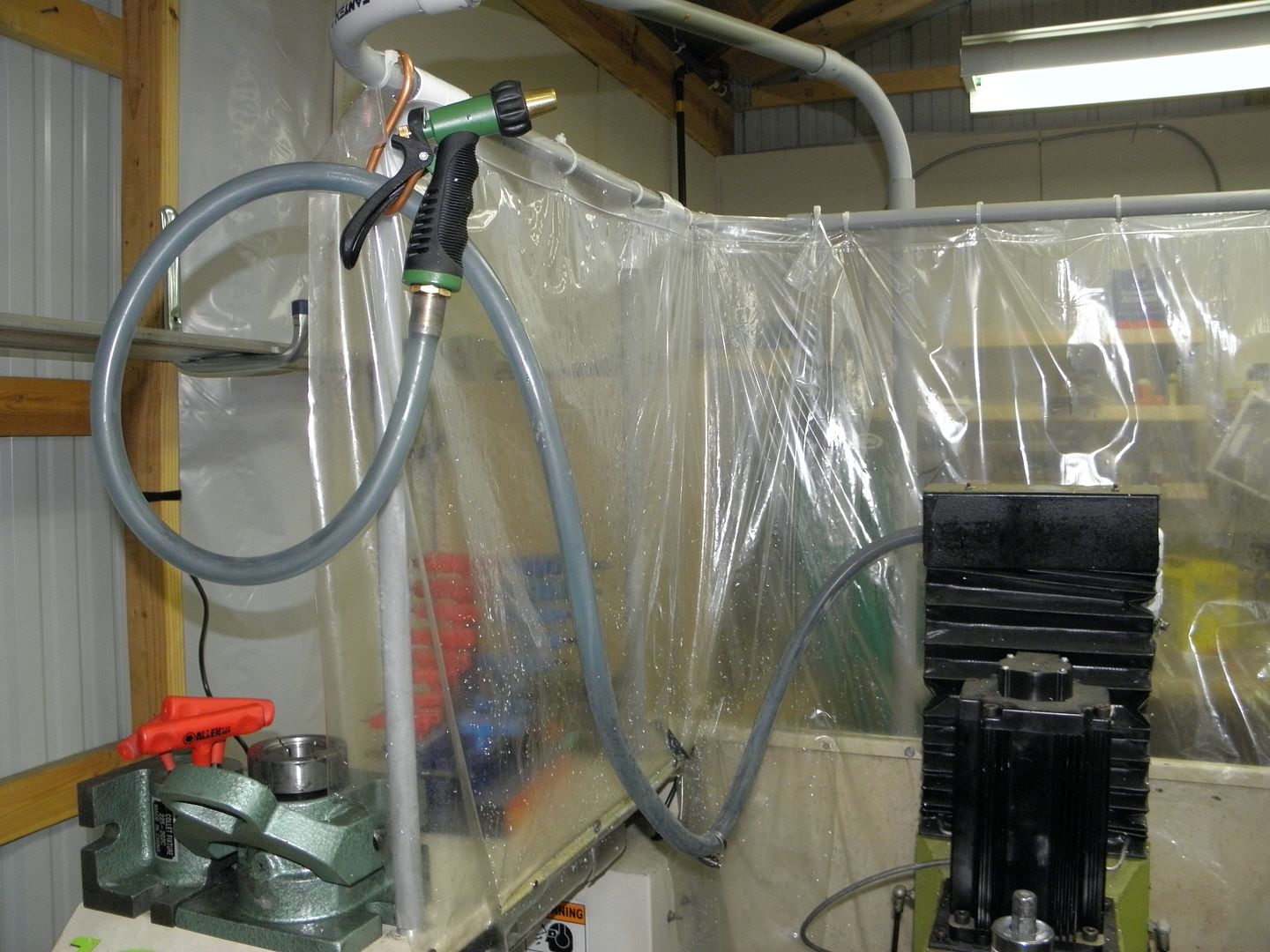
So much better than using air
pete
-
04-14-2013, 10:37 PM #18
Registered
- Join Date
- Dec 2004
- Posts
- 57
That looks like a fantastic idea for a coolant return upgrade which I may have to incorporate. Here's what the coolant system looks like now. Originally Posted by slowtwitch
Tormach PCNC 1100 - Further Flood Coolant System Upgrades, Maximizing Flow - YouTube
Skip to 4:30 to see the flow going into the enclosure.Christopher Anglin
www.mc2racing.com
-
04-30-2013, 10:39 AM #19
Banned
- Join Date
- Jun 2012
- Posts
- 111
Now that I have my coolant system upgraded, I am also having problems with the chips clogging the chip tray. I may have to add a 2nd drain on the RS of the machine. Is anyone working on a chip auger for the Tormach?
-
01-19-2013, 11:39 PM #20
Registered
- Join Date
- Dec 2004
- Posts
- 57
I've attached a picture which shows the differences in flow quality between the straight and 90° nozzles. When I switched the 1/4" hose to the straight nozzle, it also had the same flow characteristics as the 1/2" hose with the straight nozzle, so it's not a function of hose size.

 Reply With Quote


Similar Threads
-
RF45 Clone with full enclosure, coolant, and tool changer
By mikemaat in forum Vertical Mill, Lathe Project LogReplies: 161Last Post: 06-07-2015, 08:50 PM -
new linear way mini millw/full atc, coolant, enclosure etc.
By fixridermtl in forum Vertical Mill, Lathe Project LogReplies: 13Last Post: 06-18-2013, 05:48 PM -
Torus Pro Coolant System And Enclosure Upgrades
By SCzEngrgGroup in forum NovakonReplies: 11Last Post: 04-15-2013, 08:15 PM -
Flood Coolant System Upgrade
By saabaero in forum Tormach Personal CNC MillReplies: 15Last Post: 03-19-2011, 01:10 PM -
Taig Drainage/Coolant System-Enclosure Build~ Pictures~Video~!
By CROSSHATCH in forum Taig Mills / LathesReplies: 25Last Post: 01-16-2008, 12:58 AM
