


I'm struggling to draw the teeth on a pinnion spur gear. I used this webpage as tutorial, but ran into problems at step 10. The webpage says the following, but leaves out the "chart" on which to look up the (R) and (r) values.
Does anyone here maybe have a chart such as this in which there's values to apply to the diametral pitch in order to calculate the radii of the tooth sides in the addendum and dedendum of the gear? Another method to achieve the same results are also welcome, if you can't help me with this chart or if you think the method on the webpage is flawed. How would an engineer draw a gear?Now, to draw the sides of the tooth:
10. Using a chart (either given to you or in a text) find the (R) radius for the addendum curve and the (r) radius for the dedendum curve of the gear tooth. In this example, the R for a gear having 30 teeth = 4.06 and the r for the same gear = 2.76.
To get the radii to be used:
R ÷ DP = 4.06 ÷ 5 = .812
r ÷ DP = 2.76 ÷ 5 = .552
Also, is the method for calculating the tooth shape of an internal gear the same as that of a "normal" gear?
Results 1 to 5 of 5
-
06-23-2008, 12:16 PM #1
 Registered
- Join Date
- Jun 2008
- Posts
- 1
..the teeth on a pinnion spur gear...
-
06-24-2008, 09:16 AM #2
Member
- Join Date
- Jul 2003
- Posts
- 1220
This method appears to be a approximate profile as the curve should be a involute.
Not sure how the R and r are calculated.
Check this web site for details.
http://www.qtcgears.com/RFQ/
See 3. Details of Involute Gearing
Here is a macro:
MACRO to GENERATE INVOLUTE PATH with SOLIDWORKS
===============================================
Sub main()
Set swApp = Application.SldWorks
Set Part = swApp.ActiveDoc
'----------
R = 71.6034 'ENTER BASE CIRCLE RADIUS
pi = 4 * Atn(1)
For Ang = 0 To 45 Step 2
X1 = Cos(Ang / 180 * pi) * R
Y1 = Sin(Ang / 180 * pi) * R
Opp = R * 2 * pi
Opp = Opp * (Ang / 360)
Hyp = Sqr(R ^ 2 + Opp ^ 2)
Ang2 = Atn(Opp / R)
Ang2 = Ang2 / pi * 180
Ang3 = Ang - Ang2
X2 = Hyp * Cos(Ang3 / 180 * pi)
X2 = Int(X2 * 10000 + 0.5) / 10000
Y2 = Hyp * Sin(Ang3 / 180 * pi)
Y2 = Int(Y2 * 10000 + 0.5) / 10000
XX = X2 / 1000
YY = Y2 / 1000
Part.CreateLine2 X, Y, 0, XX, YY, 0
X = XX
Y = YY
Next Ang
'----------
End Sub
-
07-09-2008, 07:49 AM #3
Registered
- Join Date
- Mar 2004
- Posts
- 150
You can plot the points of a true involute from the base circle by the method of conventional drafting described in the machineries handbook.
Then calculate a standard circular thickness (this is ARC length) and convert it to an angle based on the pitch diameter. Mirror the involute around the mid point of the angle created, and throw a radius in the bottom (also a calculation) and whalla.
Keep in mind the radius at the bottom will not be quite like the one a hobbing machine would form.
-
07-13-2008, 09:45 PM #4
Registered
- Join Date
- Sep 2006
- Posts
- 36
 Drawing gear teeth.
Hello, It's one of several aproximations, using a circular arc to represent the involute curve. Do not use that one myself, I take points on the involute, calculated with a simple spread sheet taking into account tooth thining (backlash), a three point curve using actual points from the involute can be used to make gears of fair but lower quality, five points, creating two curves will give a form with a couple of ten thousandths. A good general root fillet will be .3/Diametral Pitch. The Internal gear is done the same way. As has been stated, draw one side, mirror, add fillet, radial copy or whatever.
Drawing gear teeth.
Hello, It's one of several aproximations, using a circular arc to represent the involute curve. Do not use that one myself, I take points on the involute, calculated with a simple spread sheet taking into account tooth thining (backlash), a three point curve using actual points from the involute can be used to make gears of fair but lower quality, five points, creating two curves will give a form with a couple of ten thousandths. A good general root fillet will be .3/Diametral Pitch. The Internal gear is done the same way. As has been stated, draw one side, mirror, add fillet, radial copy or whatever. Originally Posted by malJohann

Cheers,
Les H.
-
07-13-2008, 10:22 PM #5
Registered
- Join Date
- Sep 2006
- Posts
- 36
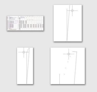
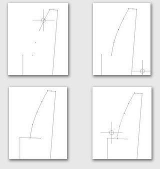
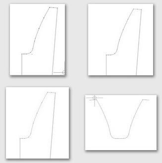
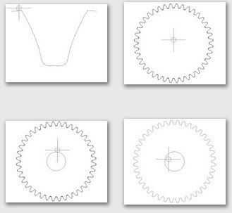
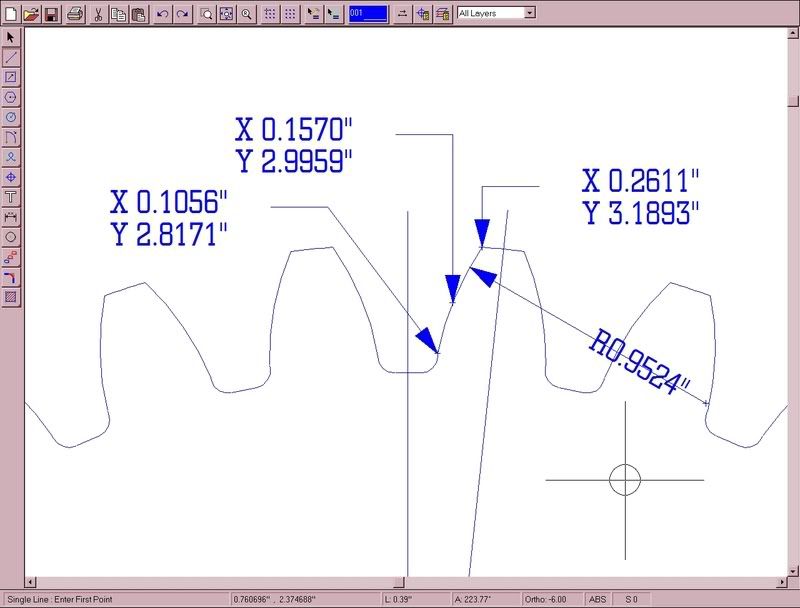
30 TOOTH 5DP 20 PA GEAR
So, calcutate points. arc. mirror, copy rotate.
[

Cheers Les H.

 Reply With Quote
Similar Threads
-
Simple spur gear design
By kentavv in forum MetalWork DiscussionReplies: 14Last Post: 07-10-2014, 02:51 PM -
Basic Bevel Gear - Milling a valley for gear teeth
By ngr1 in forum Uncategorised CAM DiscussionReplies: 10Last Post: 04-05-2012, 03:55 PM -
Diameter, Pitch, Number of Teeth, etc. on Spur gear?
By SlimJimmy in forum Waterjet General TopicsReplies: 15Last Post: 12-04-2008, 05:10 AM -
Spur gear availability?
By 2fst4u in forum Waterjet General TopicsReplies: 3Last Post: 04-02-2007, 02:46 PM -
Spur Gear / Gear Rack
By ckrantz in forum Linear and Rotary MotionReplies: 12Last Post: 12-07-2006, 06:06 AM
