


I was inspired by JBV and his thread on building a servo motor. I started researching the subject and became engrossed with the idea of building a servo motor. I just need a couple things filled in. I'm not sure whether to go DC brushed or AC brushless yet. I have heard about the low RPM's and cogging with DC brushed, but I have experience with retrofitting some decent regular DC motors with encoders and gecko's, and down to 1 rpm, I didn't see any cogging. Just smooth motion. I don't know when i'll ever run it that low machining, but they seem to do just great. Although, without a scope, I can not apparently tune all the resonance out of them. If you put your hand on the motor, you can feel a slight hum.
But, I digress. So after spending hours on the rcgroups.com forum, and learning a ton about the LRK motors, basically AC brushless, I took apart one of the actual DC brushed servo motors I have. Just a few questions.
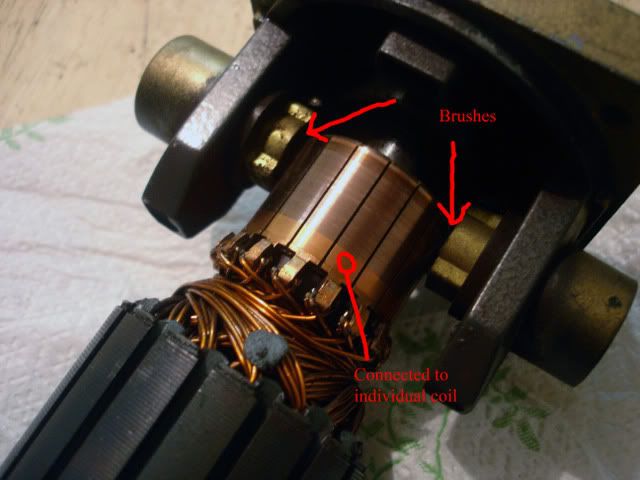
I have a question about the commutation. Based on my research (and some guessing), I believe the brushes come in contact with each individual copper tile, and trigger opposing tiles every increment. I counted 16 individual "poles," although I don't think that's what they are called. If someone can confirm or elaborate on this, I would greatly appreciate it. Or, point me to some site that explains it well. (Preferably in english, I see a lot of great german sites. They must love building their own motors!)
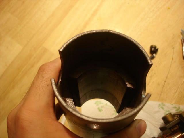
Next, is the magnets.
This has two large manets, opposite each other. One observation is that on the inside of the motor housing, the magnets are pretty strong. But on the outside, nothing is attracted to it. How does this work? Also, is the number of magnets determine how many "pole's" there are? I know you want as many poles as possible, for positional accuracy. Again I go back to the DC motors I have, they start and stop and position great, excellent acceleration also. They have two magnets, so I'm not quite sure if that makes a difference. I noticed a lot of the homemade motors have as many magnets and they do those loops of wire. I found a great place on the rcgroup place that has any and every kind of Nd magent I would need, and nicely priced also.
My goal is to create a decent powered, 250 oz constant, 1000 oz peak servo. The DC motors I have are great, but they are 4 inches in diameter, and about 9 inches long. A bit too much for the IH mill. I want a more compact motor, but with plenty of power. Plus, I would love to build my own motors, just for the excitment and project. I'm sure I could, and have found motors that will cost the equivalent. I'm in this for a hobby, and love to learn!
Which brings me to the subject of "hall commutation." I believe this is for AC motors. If I go the AC route, with AC drives, I don't know squat about the commutation for that. Any good links or resrources would be greatly appreciated. Maybe even some places that sell what I would need.
I'm not worried about the tooling required to build it, because I have the 3 axis mill, and plan getting a lathe shortly. Oh, and I should mention that the DC servo I took apart, it's 12V at 20 amps, for 100 oz continuous at 2100 rpm's. My DC motors are great, but they are 120V, at 3200 RPM's. So with the gecko's, I can only get about 1700 RPM's out of them. I would like to play around with those numbers, and get something with a couple thousand RPMS and then gear down. Sorry for all the quesions. I plan on modeling everything up in solidworks once I decide on brushed or brushless. That won't take too long.
Again, thanks in advance for the suggestions, and look forward to working on this project! :rainfro:
Thread: Servo motor build project...
Results 1 to 14 of 14
-
11-22-2006, 09:37 AM #1
 Registered
- Join Date
- Sep 2005
- Posts
- 249
 Servo motor build project...
-
11-22-2006, 04:05 PM #2
Registered
- Join Date
- Dec 2005
- Posts
- 3319
Difficult topic but in an economy of words:
A brushed DC motor cogs because of the number of armature poles that go into and out of (plug) the magnetic field per revolution.
A 3 pole/3 commutator motor (typical r/c car motor) cogs badly because so few armature bars rotate witin the field.
A precision can model train motor has 5 poles and is much smoother - less cogging because the poles overlap more AND they skew the armature laminations (// versus II) which softens the cogging.
A servo motor has many more poles than a simple DC motor- count the bars on one and you'll see.
The fact that there is always a pole plugging the magnet results in smoother repulsion of the armature pole from the magnet which is how/why a motor works anyway. Moreover, the plugging is essentially overlapped. Sort of why a 4 cyl engine of same displacement is MUCH rough running than a V-8 of same displacement - the power pulses are better overlapped thus it feels smoother while running.
THus, if you're going to make a brushed DC servo, you want a high pole count motor. THis is why treadmill motors make decent candidates - high pole counts. BUT, they can have a lot of inertia which makes them poor candidates. You want intertia on a tread mill to keep the motion smooth - you don't want ineratia on a servo due to rapid need to change direction and speed.
The reduction in inertia is why servo motors tend to be long in length and small in diameter.
I don't know if tread mill motors are well suited to direction reversal (that involves brush timing/orientation and other issues too complicated to discuss).
Brushless involves intense matcing of motor to drive for proper commutation - I'll let someone else explain. For DIY first time, you're cost and time ahead to stick with PMDC motors.
Re; magnet count and loops of wire:
Motors typically have poles as multiples of 2. You picture shows 2 magnets which yields one N an S pole (the case provides the magnetic return path). There are cases with 4 magnets but these have two N and S poles opposite each other.
THe magnet can be a permanent magnet (your foto) or can be created by winding a coil of wire around and iron core. The current that feeds the armature also goes thru the wound field to create the same mag field as the PM's do.
Investigate "permanent magnet DC motor" and "shunt wound DC motor" for more details.
-
11-22-2006, 04:54 PM #3
Registered
- Join Date
- Sep 2005
- Posts
- 249
Thanks for the reply NC! I love reading your posts. I can see what you're talking about with the skewed rotor, the nicer DC motors I use as servos are like that. Based on the commutation, I think a PMDC motor will be easier to start out with. I will be looking to make it multiple pole, and possibly with 4 brushes, but we'll see how complex designing something like that is. The DC servo I took apart seems simple enough. I'm now investigating how many turns and size I need for a given RPM and voltage.
Would a DC motor benefit from better magnets? Like the Nd kind. I know that none of the DC motor's I have use those. They seem like common rare earth magnets. I think I would like to design it so that the coils are on the stator, and magnets on the rotor. That way I could potentially put a water jacket on the motor for cooling. Just throwing out some ideas. I wan't to try and compact the size as much as possible. Back to my researching!
-
11-22-2006, 10:15 PM #4
Banned
- Join Date
- Sep 2005
- Posts
- 229
Hello!
 I intend to go for BLDC! Check this out! Seems to be pretty easy to get it working, just add 3 hallsensors!
-
11-22-2006, 10:23 PM #5
Registered
- Join Date
- Sep 2005
- Posts
- 249
What language is that?
I would love to go the brushless route, as I see most huge VMC's and what not with AC Digital servo's. They must use them for a reason. But I don't know what hall sensors are. I'm trying to find simple documentation on them, any steps in the right direction?
-
11-22-2006, 10:42 PM #6
Registered
- Join Date
- Sep 2005
- Posts
- 249
Ahhh, i see now. I found some good documentation on hall sensors, and I understand a bit more now.
So does the hall sensor act like an optical encorder on a brushed DC servo? Would you therefore not need an encoder on the AC motor with hall sensors?
I am still looking for a source to buy these sensors, and then would have to source drives for them also. I'll have to check, but the drives Xerxes is working on should work fine. So, I guess I'll see how much more these hall sensors end up being.
Another observation. One of the negatives people claim about brushed motors, is that the brushes will wear out, and the efficiency is decreased because they come in contact with the rotor. First, I have run my motors a bit, and based on the size of the brushes, it seems it would be forever before they ran out. Is there a typical hour/life time for them? Are they all made of the same carbon/copper stuff? Secondly, I like the idea that the hall sensors are not in contact with the rotor, but do the brushes create that much friction? An interesting journey this is turning out to be.
-
11-22-2006, 10:51 PM #7
Banned
- Join Date
- Sep 2005
- Posts
- 229
Its Swedish..
The sensors just tell the controller what phases to drive. You still need a encoder!
-
11-23-2006, 12:29 AM #8
Registered
- Join Date
- Dec 2005
- Posts
- 3319
Brush friction: the R/C car racers studied brush friction until it hurt. More graphite in brush gave less friction but also didn't pass as much current as brushes with a higher copper content.
Yes, 4 brushes will have more friction than 2 BUT you'll have twice the current flowing potential, especially with a 4 pole magnet setup - more current equates to more torque so it more than makes up for the extra friction.
The copper/graphite mix is varied all over the place to suit the needs/operation of the motor. Copper brush on copper commutator bars don't wear well nor do they have low friction BUT they pass lots of current.
Don't get involved with messing with brush compounds. use what came with the motor, especially if it is an industrial grade brush/armature package.
As far brushed servo motor life goes, I have a Bridgeport mill that was new in 1996 and it is only on its second set of brushes. This brush wear thing that guys make an issue over is somewhat overrated (IMO). Are you making a Haas or is this just a DIY project???
If it is a project, I'd be inclined to use a PMDC until you learn how to deal with/tune/apply servos, then go rocket science and get involved with BLDC.
BTW, some of the Haas machines (real high end, no???) were factory fitted with PMDC motors. Food for thought....
BTW; if you want to reduce/minimize brush wear, you can do some fancy commutator polishing and low speed comm burnishing. Brush wear becomes negligible when you do that.
The factory comms are made a bit rougher becuase it is impractical to lap/polish copper comms - they actually sometimes use specially compounded brushes (grittier when new and then they get finer/smoother) so as to burnish the comm while it runs.
Whenever I replace brushes in a motor, I burninsh the comm if at all possible (fine finer and finer yet w/d sand paper) and make sure it is round and smooth - typically you see a noticeable difference in torque, reduced brush arcing and definitely lower brush wear potential.
I'd contend that a PMDC motor is perfectly FINE for the beginner and even the more advanced if cost is an issue - PMDC is usually the value priced motor for DIY CNC.
-
11-23-2006, 01:30 AM #9
Community Moderator
- Join Date
- Dec 2003
- Posts
- 24220
DC servo brushed motors generally have two sets of brushes set at right angles, you will find two Pairs PM poles, this together with skewed rotor laminations , increased number of armature poles, and brushes that overlap the commutator bars, create a very smooth rotary motion down to extremely low rpm.
In the case of AC servo's, there are two distinct type that are constructed almost identical, the BLDC Brushless DC and AC Sinusoidal.
Think of a BLDC as a brushed motor turned inside out, the commutation is now electronic, and the PM fields are on the armature.
The (old) hall effect detectors are used to detect the position of the permanent magnet position of the rotor. So the correct stator winding can be energised.
If the BLDC has one pair of poles then there is one electrical revolution/pair of poles for every mechanical revolution. Every pair of poles will increase this and create better resolution, (less cogging).
Nowadays the encoder and the 'Hall effect' tracks are combined, (see Renco site for details).
Although a BLDC and a AC servo are constructed as a 3ph motor, it is called 'Brushless DC' due to only two windings energised at any given time.
With a 3ph sinusoidal, it is a true 3phase motor and will give excellent response down to zero rpm.
The beauty of BLDC and AC servo is the lower inertia and the fact the windings are on the stator, so cooling can be maximized, (smaller motor).
I would consider a BLDC the easiest motor to make, but Magnets are going to be a problem for home built, whatever the type.
Another thing to consider when dismantling a servo motor (although modern ones do not suffer as much) is that you can get PM loss when you remove the armature as it act as a keeper, so you may want to insert a ferrous metal bar in the the armature space while the motor is dismantled.
Al.CNC, Mechatronics Integration and Custom Machine Design
“Logic will get you from A to B. Imagination will take you everywhere.”
Albert E.
-
11-23-2006, 01:44 AM #10
Registered
- Join Date
- Sep 2005
- Posts
- 249
Thank you both for the excellent posts. The thought of having the coils on the outside, putting the magnets on the rotor, and then using a water jacket to keep it cool and boost power came to mind while researching. It seems as long as you can keep it cool, you can put A LOT more into it. Though, I don't to bother with 6 more hoses and a cooling system, much more make the jackets. I think I will go with the brushed DC motor, simply because I already have the gecko's, and have a couple DC motor's for examples. Can't find a good diagram of a 4 pole motor, but as long as I know they're offset 90 degrees, that should work.
I was playing with the disassembled motor and noticed something else. Using a voltmeter, I was testing for continuity. I know that the coils are isolated form each other on the rotor, but they all come together on the commutator. Plus, the + and - are would be connected "shorting" as it spins. Does the commutator in fact connect all the windings, and you simply don't want them to short across the rotor? I see the little gaps between the commutator plates, but the brushes overlap on those plates. I still have a ways to go!
It makes since now that the brushes wouldn't have "100% flow" of current, so 4 would be better. I understand now why that would be another advantage to AC. That's a great tip on buffing the commutator and burnishing the brushes, makes perfect since!
Although, this is just a hobby mill, and I would love to get into starting a side machine shop, this is not going to see heavy production, or need to hold .0001" all over the place. It is just a hobby for now. But like NC said, I'll take on the rocket science after finishing this project. I have no idea how the drives work, so that would take a while also. I don't even have huge power requirements for these motors, just want something more compact and the benefit and satisfaction of knowing I had more to do with my CNC conversion!
-
11-23-2006, 01:52 AM #11
Community Moderator
- Join Date
- Dec 2003
- Posts
- 24220
The reason for the commutator is to create the right (90°
 vector between the energised armature pole and the PM pole, when an energised pole is attracted to the opposite PM pole it moves toward the PM pole and another armature pole is place under the brushes, hence constantly maintaining the optimum vector.
Al.CNC, Mechatronics Integration and Custom Machine Design
“Logic will get you from A to B. Imagination will take you everywhere.”
Albert E.
-
11-26-2006, 11:26 PM #12
Registered
- Join Date
- Jul 2005
- Posts
- 450
if you are looking at this for a milling machine you might want to check out linear brushless motors and linear encoders. They work exactly the same as rotational motors, but look a lot easier to construct, as you can use off the shelf NeFeB magnets. Also you do away with the need for a screw, at the expense of a more expensive encoder. As a bonus you have absolutely no backlash between encoder reading and axis position, as they are directly coupled.
check out:
http://www.aerotech.com/products/mot...ar_motors.html
Making some is on my todo list, but have too many other projects on at the moment.(story of my life )
-
11-27-2006, 07:08 PM #13
Registered
- Join Date
- Sep 2005
- Posts
- 249
Fascinating! Definetly love the pro's of a linear motor. Didn't know they were that simple. I think I will stick with the Brushed DC motor, and then move into the AC Brushless. I'm still not even sure where the hall sensors would even go. Plus, I don't have the driver to move them. I'm dreaming about the resolution I could get with my laser table though! Although, I don't have any practical applications for that much resolution. It would be nice to not have to worry about bearings, and pillow blocks, and screws, and backlash! Lots of Pro's in my book. I'll definetly be keeping information stored away on this one. I need to find out more about "linear encoders." Are these the glass rods people talk about for DRO kits?
-
11-27-2006, 08:35 PM #14
Registered
- Join Date
- Jul 2005
- Posts
- 450
yep, the glass encoders you get with a dro would be great for such an application. You can also get quadrature encoders that are linear rather then rotary, but i havent seen any with particularly good resolution.
You mentioned a highly accurate laser table, what resolution can you achieve with it? is it a laser interferometry system? (probably spelt that wrong)

 Reply With Quote
