


Hello all!
I've been looking around for quite some time trying to figure out tool paths.
I looking into what applications can provide full contour of the part.
my aim is to carve surf boards and using a trial version of a few apps i can see most go along the axis and make the edges look terrible unless passes are excessively close.
is there any application out there that will contour things like surfboard or boat hulls?
Results 1 to 6 of 6
-
07-14-2014, 11:29 AM #1
 Registered
- Join Date
- Mar 2013
- Posts
- 10
Tool Path questions - no searches helped!
-
07-14-2014, 01:25 PM #2
Registered
- Join Date
- Jan 2014
- Posts
- 37
Re: Tool Path questions - no searches helped!
Hello are you talking about the whole surfboard? Which would be 3D freeform milling or just the contour which would be 2.5D?
-
07-28-2014, 12:21 PM #3
Registered
- Join Date
- Mar 2013
- Posts
- 10
Re: Tool Path questions - no searches helped!
Hello,
Sorry for the late reply, this is for the full 3D profile of the board.
I need something that follows the contours of the board.
I have had a look at a few other methods and they all end up with funny lines and lumps. nothing seems to contour the part in a smooth sweeping motion.
Recently I found Shape3D La r however this is so expensive its not affordable for a home user to purchase.
Any help would be much appreciated.
-
07-28-2014, 04:53 PM #4
Member
- Join Date
- Sep 2012
- Posts
- 1195
Re: Tool Path questions - no searches helped!
Do you have a 3d model of what you want to cut? If so, I can create a toolpath for you to see and show a simulation of it being cut. The simulation will also show what the final part would look like, and my experience is that it will be exactly the same as what is shown in the simulation.
As to the problems you mention, it seems like you may be talking about the ridges created between passes? If so, a larger ball cutter will produce less of the ridges and allows for a larger gap between passes before the results start to get worse. If you draw the geometry of the diameter of the ball, as well as a second ball, you can space the two diameters apart to simulate the step over from one pass to another and see what the ridge will look like and how tall it should be. In the image below, I created a 6.35mm ball diameter and a 25mm ball diameter to show a comparison of the ridge left by each size with the same 5mm step over as an example. In general, I would recommend using the largest ball cutter that you can fit into your geometry. For a surf board, there really is no limit as to the size of the cutter since there is no interior corners to get into, so the biggest ball cutter you can get would be the best. Many CNC operates mistakenly think that a smaller ball cutter will provide them with more detail. The only case where more detail can be extracted by a smaller bit is when the surface irregularities are smaller than the larger bit being compared to. In the case of a smooth surface like a surf board, a larger bit will provide exactly the same amount of detail as a smaller bit, and you can get a better finish than you would with a smaller bit.
Other than the ridges created by the step over between each pass, there is no other reason that the final part should vary from your model, so if you have found that there are other problems in the part, it is either a problem with the CAM software or a problem with the 3d model's geometry. CAM systems do not tolerate badly made geometry well, so it's critical to produce a clean model.
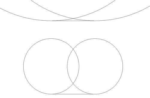 Ballend Mill by mmoe5150, on Flickr
-
07-28-2014, 08:56 PM #5
Member
- Join Date
- Apr 2004
- Posts
- 5737
Re: Tool Path questions - no searches helped!
You might take a look at DeskProto; it's a simple program to use, and you can try a fully functional version for free for a month. It's also very affordable if you're a hobbyist, which it seems from your message that you are.You need to use ball-nosed endmills, by the way - anything 3D will show a lot of toolmarks if you use flat-ended cutters. If you're averse to sanding, then yes, you have to make the step-overs pretty small, depending (as was pointed out above) on the size of your cutters. The best strategy for minimizing toolmarks will depend on how steep the curves are that you're milling. On relatively flat areas, a parallel strategy, where the tool goes back and forth over the material, will probably be fine. But towards the edges of your surfboard, where your toes would curve over it, then you might want to use a horizontal or "waterline" strategy instead, since it will put more passes of the tool into each vertical inch.
-
08-09-2014, 07:50 AM #6
Registered
- Join Date
- Oct 2013
- Posts
- 109
Re: Tool Path questions - no searches helped!
Hi Jas269,
I'm afraid this is the nature of 3D machining. If you want a good finish it takes a time. It is always a case of finding the right balance between machining time and quality of the end result. But of course chosing the correct machining strategy helps. Just a basic parallel lace would not do the job for you by the sounds of it, you need to look at wore complex strategies that attempt to keep the cusp constant.
With the materials you make surf boards from it would be impractical to have a fine stepover when you can very quickly refine the surface by hand afterwards.
If you have a 5 axis you could use a flat ended tool to machine these 3d shapes and this would greatly reduce machining time and increase quality. I have also seen surfboards machined with the edge of abrasive disks that are running at right angles to the path. This gives a vary large diameter in contact with the part.
If you give me a model a will demo a few tool paths for you.

 Reply With Quote
Similar Threads
-
This forum really helped my build so Thanks
By RiserCNC in forum Uncategorised MetalWorking MachinesReplies: 0Last Post: 10-27-2012, 12:02 AM -
Rotory tool path is posting out new cord with every path?
By metlshpr in forum MastercamReplies: 3Last Post: 10-07-2011, 05:45 PM -
Roughing tool path questions
By lpmfg in forum SolidCAM for SolidWorks and SolidCAM for InventorReplies: 6Last Post: 12-15-2010, 10:38 PM -
Thanks to those who helped
By Greg ccf in forum Bridgeport / Hardinge MillsReplies: 0Last Post: 12-19-2007, 07:48 AM
