


Hey Ya'll-
After much drooling over everyone else's CNC success with the Grizzly G0704 i've decided to start my own build.
Today I was attempting to hookup and test my stepper motors but I'm running to trouble. Nothing moves!
My gear is as follows,
- Old POS PC running windows 7 32bit and Mach 3.
- This PCI LP1 Card SYBA Model SD-PCI-1P PCI to Parallel Port Card Add-On Card - Newegg.com
- KL600-48 power supply
- MX3660 driver and BOB
- Nema 23- 570 stepper
I have the MX3660 being powered by 48V (verified by meter). It powers up fine. When the MX is powered up I here a clicking noise from the stepper and I am unable to move the shaft (good news right?) I have the e-stop circuit jumped to eliminate the Mach error. DB25 cable from the MX to computer has been pinned and all pins show continuity as expected. Under Mach's ports and pins setting I have the correct location 0x378 (LP1) chosen. This has been verified in windows device manager. Under Mach's motor setting I have the rev's per set to 2000, pulse uS set to 5 and dir uS set to 5.
When I bring up the jog screen (tab) and press the arrow keys to job the X-axis the stepper which is connected to motor 1 of the MX, it does not step. I have read in the MX3660 manual that pin 2 is pulse and 3 is direction. These have been set correctly in Mach for the X axis. I have tried the "Low" toggles on and off to no avail....I'm beginning to think my Parallel port just is too "Modern.........".
Any suggestions?
I'll be sure to post pictures as I continue my build.
Thread: G0704 CNC Build (CountryGib)
Results 1 to 19 of 19
-
06-22-2014, 12:20 AM #1
 Registered
- Join Date
- Jan 2009
- Posts
- 16
G0704 CNC Build (CountryGib)
-
06-25-2014, 02:37 PM #2
Registered
- Join Date
- Nov 2012
- Posts
- 174
Re: G0704 CNC Build (CountryGib)
One quick thing to try is to put your meter on the Direction pin and see if it goes High/Low when you press the opposite movement arrow keys. If you see nothing, then the problem is in the parallel port card installation or Mach3 setup. Check the Windows device manager to see if the card is recognized by the system. If it is, then please post a screen shot of your settings. One mistake I made when I first hooked up was not setting the Port number to 1 (it is set to zero by default) in each pin's configuration. --md
-
06-25-2014, 02:45 PM #3
Registered
- Join Date
- Jan 2009
- Posts
- 16
Re: G0704 CNC Build (CountryGib)
Thanks mduckett. I actually solved it moments after posting. I did not have the address set correctly in Mach3. for anyone else struggling it is the first hex code in the device manager resource window for the PCI card you are using. My address was something weird like Cx800 instead of the typical 0x378 or 0x278.
Right now i'm trying to understand the workings of home switches. Does anyone have stellar links or guides for this dummy? Mcmastercarr links would be epic.
-
06-25-2014, 03:08 PM #4
Registered
- Join Date
- Sep 2012
- Posts
- 323
Re: G0704 CNC Build (CountryGib)
McMaster-Carr
I wouldn't buy any from them though. I'm sure they are good, but man are the prices crazy!
I got my from automationdirect.com for about $15 each.
Andrew
-
06-26-2014, 04:57 AM #5
Registered
- Join Date
- Nov 2012
- Posts
- 174
Re: G0704 CNC Build (CountryGib)
I'm using the sub-miniature switches from McMaster-Carr, here: McMaster-Carr. Mcmaster costs more, but where I'm located I usually get overnight delivery for ground UPS shipping cost. It's a good idea to house these switches to keep out chips and possibly coolant if you use mist or flood. I'm using the traditional 2 switches per axis, but Hoss and others are using a nice setup that uses only one switch per axis to save on inputs, just search his thread for limit switches. If you search CNCZone for "limit switch wiring" you'll get tons of info too. I'm using normally closed switches (NC), with the input pulled up to 5V with a 4.7K resistor, and the closed switch connected to ground. The input to the computer shows normally Low unless the switch is activated (opened) and it changes to High. Lots of different ways to wire them up though. --md
-
06-26-2014, 08:48 AM #6
Registered
- Join Date
- Sep 2012
- Posts
- 323
Re: G0704 CNC Build (CountryGib)
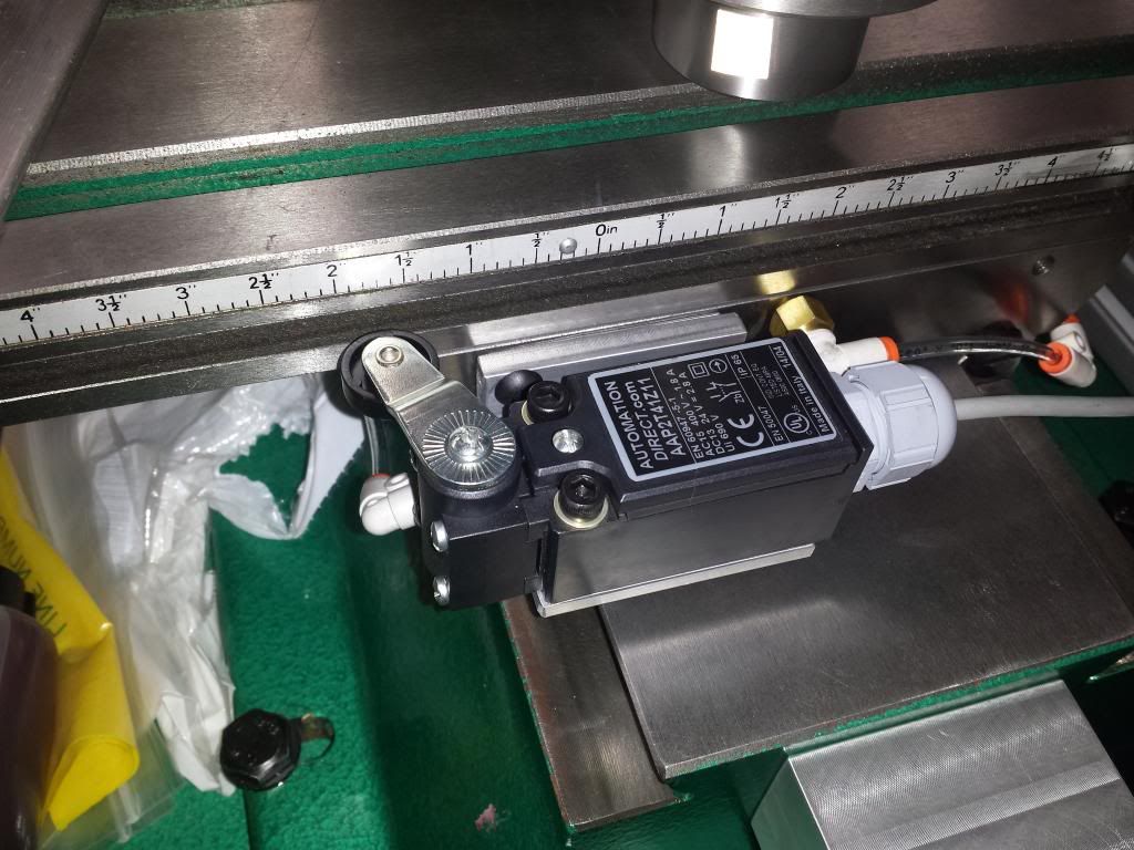
I had picked up some switches like that as well. But in the end went with the THIS one form automation direct. It is IP65 rated, so flood coolant should not be an issue. And another member on here said he has been using them for years with flood without covering the switches. Originally Posted by mduckett

Also, since you are using the MX3660, you shouldn't need to play with resistors on the inputs. I only have one switch fully setup on my machine at the moment but it works great so far. I only plan to cover the x switch because I want to cover the ball screw to keep chips out of there. The Y and Z will be out in the open.
Not sure if this is the kind of info you were looking for...... or just general info on how they work and what they do.
Andrew
-
07-02-2014, 04:36 PM #7
Registered
- Join Date
- Jan 2009
- Posts
- 16
Re: G0704 CNC Build (CountryGib)
Hey Wiggles-
Nice location on the x-axis. Totally going to copy this. Are you also using that switch for homing or just limit? I sense the repeat-ability of this switch is not very great. If I want to use optical switches for homing which do ya'll suggest?
Matt
-
07-02-2014, 06:38 PM #8
Registered
- Join Date
- Sep 2012
- Posts
- 323
Re: G0704 CNC Build (CountryGib)
Homing and limit. I can't really comment on the repeatability yet as I still don't have my machine dialed in. but I would imagine it would be just the same as any other mechanical switch.
Andrew
-
07-11-2014, 05:13 PM #9
Registered
- Join Date
- Jan 2009
- Posts
- 16
Re: G0704 CNC Build (CountryGib)
Hey Dudes. I've got my mill up and running and had an accident. Turns out that piece of crap drill chuck that came with the G0704 should have stayed in China. Long story short I crashed my mill and the Oldham connection disc slipped from position on the Z-axis. Upon trying to correct the problem I'm having a fun time removing the coupling from the stepper motor shaft. Both set screw are loose and as goose. I've tried prying and vice grips. The kicker is I cannot remove the cap from BDtool's mount until I remove the coupling. So the motor is trapped on the mount. Any suggestions? I really don't want to have to cut and grind the coupling.
Attachment 242118
On a side note. I made a not so pretty mount for the X-axis limit and home switch. Repeatability is within .0005 with backlash in MAch3 set to .002 as measured.
thanks dudes,
MJ
-
07-11-2014, 07:54 PM #10
Registered
- Join Date
- Nov 2012
- Posts
- 174
Re: G0704 CNC Build (CountryGib)
Looks like the motor side coupler tried to turn against a locked shaft and was forced by the insert up the motor shaft? The set screws must have dragged a burr that has wedged it all tight. I was thinking you could remove the motor bolts and pull it up until the coupling bottoms out, then maybe get enough angle to tap the end of the shaft with a punch? Don't want to drive too hard on the motor shaft to save the bearings. Maybe the screw side coupler could come out to make more room? Some heat on coupler might help to expand it relative to the shaft. Turning the coupler opposite the direction that it was spun up might work too as it is sort of theaded onto the burr. My 2 cents, sorry for the troubles, let us know how it works out. --md
-
07-11-2014, 08:14 PM #11
Registered
- Join Date
- Jan 2009
- Posts
- 16
Re: G0704 CNC Build (CountryGib)
I think my plan is going to be lock the nubs on the coupling with a vice grip and run the stepper opposite the direction it was running when I crashed it.....fingers crossed. Now just 2 more hours of work. gaaahhhllll
-
07-25-2014, 01:10 AM #12
Registered
- Join Date
- Jan 2009
- Posts
- 16
Re: G0704 CNC Build (CountryGib)
Hey Ya'll-
I was able to reconstruct my Z-axis with a bit of propane and flame. Now onto a task I am completely clueless on,
I'm trying to use Mach3 to control the spindle using the stock G0704 motor and drive. My MX3660 breakout has a 0 to 10V output but i am clueless how to hook it up.....I've attached some photos of all 3 boards that are a possibility for connection.
Can someone walk this dummy through what each board does and how I should connect the MCX3660 and what I should do within Mach3.
MJ
-
07-25-2014, 03:28 AM #13
Registered
- Join Date
- Jan 2009
- Posts
- 16
Re: G0704 CNC Build (CountryGib)
Update: I was able to gain control of the stock spindle by pulling constant voltage from pin P3 which was placed into the +10V input on the MX3660. Ground pin P1 was connected to ground on the MX3660. Reference voltage from the MX3660 was connected to pin P2.
It works! I can control speed from Mach3. However stopping the spindle completely is a challange. I see in Mach3, code "M3" is linked to the output #1. My question would be what does output #1 do and how can I connect it to the g0704 motor control board....I guess I need to rig up this output signal to fake me pushing the on off button?
I hope someone can chime in.
MJ
-
07-25-2014, 04:20 AM #14
Gold Member


- Join Date
- Feb 2007
- Posts
- 4553
Re: G0704 CNC Build (CountryGib)
MJ, Originally Posted by CountryGib
Using a 24v d.c.relay would work, using the connection for the guard switch to turn the spindle on or off.
Something with a low current coil, like a srd-24vdc relay, see attached link:
srd-24vdc relay | eBay
or even a pre assembled board like:
1 Channel 24V Relay Shield Module for Arduino Arm Pic AVR DSP SRD 24VDC SL C New | eBay
The MX3660 output is limited to 24vdc at 70ma max
Hope this helps.
Jeff...Patience and perseverance have a magical effect before which difficulties disappear and obstacles vanish.
-
07-28-2014, 03:02 AM #15
Gold Member
- Join Date
- Feb 2007
- Posts
- 4553
 incomplete information
A 24 volt d.c. power supply is required to power the relay.
The MX3660 outputs are pull down, they do not provide power.
Sorry for the incomplete information in the previous post.
Jeff...Patience and perseverance have a magical effect before which difficulties disappear and obstacles vanish.
-
08-14-2014, 02:09 PM #16
Registered
- Join Date
- Jan 2009
- Posts
- 16
 Re: G0704 CNC Build (CountryGib)
Morning Gentlemen,
I need a recommendation or wisdom on what is going on here.
I've got the BDtool's kit on my G0704 but the backlash in the X is 0.0085 and Y .0135 completely unacceptable. I got to tinkering and noticed the bearings provided have noticeable slop. I can visually feel and see the slop when I lightly push on the end bearings.
Does anyone have a suggestion on upgraded bearings?
I had an idea to put lighduty belleville springs on both interior ends of the X axis ball screw. Essentially cinching the table to the ballscrew and removing possible bearing slop. Also this idea will balance the travel forces. When the table move right the right bearing will be pushed. When the table moves left bearing would be pushed. Right now only the right bearing is only doing the pushing and pulling, I feel this has led to some fatigue issues which is why the bearing is sloppy now.....thoughts?
-
08-15-2014, 04:21 AM #17
Member
- Join Date
- May 2008
- Posts
- 1185
Re: G0704 CNC Build (CountryGib)
I found that type of bearing to have about .0015" to .002" slop. For CNC that's not OK for me. You have more slop than that so the ball nuts should be giving you the rest.
Pull one of the ball screws and remove the seals from the ball nut and feel for play, it's a bit of a pain to re pack them and get the right size balls but that's the system.
If the end of the ball screw is square you can put a indicator on it and check for lash coming from the end bearing.
To fix the end bearings you can go to two A/C bearings but you need to shim the outer race or grind the inner race on one bearing. I did one like that and the shim was almost see through. It might be easier to do a offset shim. Use a ground washer or a good flat one and remove .002" from the inside mating surface to preload the end bearings.youtube videos of the G0704 under the name arizonavideo99
-
08-15-2014, 08:01 AM #18
Gold Member
- Join Date
- Sep 2009
- Posts
- 1856
Re: G0704 CNC Build (CountryGib)
the bearing does not look like its retained very well (not locked in place very well) have you tried putting a washer between bearing and the bolts its a dirty way of doing it but if it gets ride of the slop you have your answer
http://danielscnc.webs.com/
being disabled is not a hindrance it gives you attitude
[SIGPIC][/SIGPIC]
-
08-31-2014, 10:01 PM #19
Registered
- Join Date
- Jun 2005
- Posts
- 49
Re: G0704 CNC Build (CountryGib)
This is interesting to me as i stuck my meter on my speed control pot (ama25lv) which looks to be remotely similar and the pot has a full live (220v) across it.

 Reply With Quote
Similar Threads
-
Jviss' G0704 Build
By jviss in forum Benchtop MachinesReplies: 23Last Post: 10-12-2012, 02:28 AM -
G0704 build
By USN in forum Benchtop MachinesReplies: 16Last Post: 09-10-2012, 05:53 PM -
G0704 - CoB's Build
By cobmachine in forum Benchtop MachinesReplies: 48Last Post: 06-20-2011, 08:34 PM -
Grizzly G0704 Build
By nocashvalue in forum Benchtop MachinesReplies: 22Last Post: 11-16-2010, 04:33 AM
